


One of the supposed advantages of centrifugal pumps when compared to positive displacement pumps is their ability to operate across a wide flow range. Because a centrifugal pump operates at the intersection of a pump curve and a system curve, varying the system curve allows the operating point of the pump to change easily using the discharge valve.
The convenience and simplicity of flow control by throttling the discharge valve comes at a price because a pump is forced to run either to the left or right of its best efficiency point (BEP). However, the real danger of operating the pump too far off the BEP is suction side issues. If it operates too far to the right, the pump may exhaust its net positive suction head available (NPSHA), which may result in cavitation. If it operates too far to the left, flow recirculation at the impeller eye will occur and cause noise, vibration and damage. Therefore, the flow must be limited on both sides of the BEP (see Figure 1).
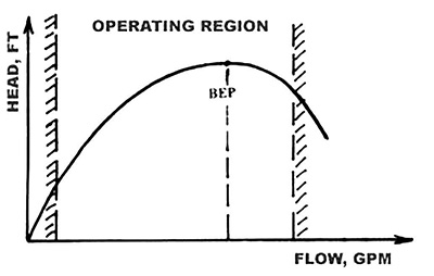 Figure 1. Pump operating range limits
Cavitation Formation
To avoid cavitation, suction pressure alone is not what is most important. How much higher the suction pressure is than the vapor pressure of the liquid being pumped is what must be considered. Net positive suction head (NPSH) is used. The NPSHA, therefore, is the difference between NPSH and vapor pressure, expressed as head in feet.
Pump manufacturers conduct tests by gradually lowering the suction pressure. As pressure decreases (the NPSHA lowers), nothing obvious happens. A pump, operating at a set flow, continues to pump and develops constant head. When the value of the suction pressure and corresponding NPSHA reaches a certain value, the pump head begins to drop, which typically happens suddenly (see Figure 2).
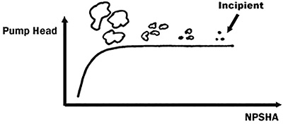 Figure 2. The development of cavitation
The formation of cavitation begins inside the pump well before the sudden drop of head, but it is not initially obvious. First, at substantial suction pressure, small bubbles form. This is called incipient cavitation—similar to the tiny bubbles in the water in a kettle that begins to percolate before the water is fully boiling. These small bubbles form and collapse at very high frequency and can only be detected with special instrumentation.
As pressure decreases further, more bubbles form. Eventually, so many bubbles have formed that the pump inlet becomes vapor locked. No fluid can enter the pump, and the pump stops pumping. The head drops and quickly disappears. Ideally, enough pressure would always be available at the suction so that no bubbles ever form. However, this is not practical, and some compromise must be reached.
NPSHR
The Hydraulic Institute (HI) has established a special significance to a particular value of NPSHA at which the total developed pump head drops by 3 percent. The value of this NPSHA, at which a pump loses 3 percent total dynamic head (TDH), in excess of its vapor pressure, is the net positive suction head required (NPSHR) to maintain a 3 percent TDH loss.
NPSHR = (Hsuction – Hvapor), required to maintain 3 percent TDH loss
NPSHR is, therefore, established by a test and may vary from one pump design to another. In contrast, the NPSHA is not related to a pump type but is strictly a calculated value of total suction head over vapor pressure. Clearly, the NPSHA must be greater than the NPSHR for a pump to deliver a TDH at a given flow.
NPSHA Margin
Detecting NPSH problems is easy—a pump stops pumping. However, the vapor bubbles do not need to be dramatically developed to cause TDH drop—even smaller bubbles can cause pumping issues. If the pressure shock from the bubbles’ collapse occurs near the metal impeller blade, it causes a microscopic impact, eroding a small particle of metal. With enough bubbles and enough time, the impeller vanes can be eroded quickly, a phenomenon known as cavitation damage.
This damage potential is why an NPSHA margin (M = NPSHA — NPSHR) is important. This margin is typically at least 3 to 5 feet, and if possible, it should be higher (see Figure 3).
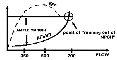 Figure 3. Ample NPSHA margin is important.
The NPSHR was limited to a particular flow on a pump performance curve. At higher flow, the internal fluid velocities are higher, and according to Bernoulli, the static pressure (or static head) decreases closer to vapor pressure. The static pressure, therefore, must be increased externally—a higher NPSHR value is needed for higher flows. Figure 4 shows an example of the NPSHR curve shape.
Example
A pump was procured and designed to deliver between 350 to 500 gallons per minute (gpm), and the manufacturer quotation indicated 16 feet of NPSHR at 500 gpm. Because the process later changed, more flow was required, and the discharge valve was opened to allow this pump to deliver more flow (750 gpm). However, as can be seen in Figure 4, at about 700 gpm, the NPSHR exceeded the NPSHA. The pump began to experience typical NPSH problems—noise, loss of performance and impeller cavitation damage.
Instinctively, a solution for the cavitation was to replace the original pump with a larger one so that the flow would remain to the left of the BEP. This larger pump provided the same 16 feet of NPSHR. However, at a flow rate of 750 to 800 gpm, the larger pump would never run out of NPSHA.
When a centrifugal pump operates below a certain flow point, flow recirculation in the impeller eye begins. This depends on several design factors, such as suction specific speed, but generally recirculation begins at less than 80 to 60 percent flow. It becomes quite severe at less than 40 to 20 percent. At even lower flows, recirculation may become especially severe and is known as surge-violent, low-frequency sound, accompanied by strong low-frequency vibration of the pump and piping (see Figure 4).
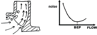 Figure 4. Problems arise when a pump operates at flows that are too low.
In addition to obvious mechanical problems with recirculation, the flow experiences a complex vortexing motion at the impeller eye with localized high velocities of the vortex causing horseshoe-looking cavitation damage, usually on the blind side of the blade, as compared to high-flow cavitation.
Identifying Cavitation
Troubleshooting methods and failure analysis techniques can help pinpoint a cavitation problem with a particular pump. The indications of high-flow cavitation are different from low-flow recirculation damage. The side of the blades and the extent and shape of the cavitation trough can be helpful in determining the causes of each problem.
At the next Pump School, I will cover specific examples that compare static-head-dominated, friction and combined systems. To register, visit www.pumpingmachinery.com.