


The design of pump inlet piping defines the resulting hydraulic conditions experienced at the pump inlet/impeller. If the design fails to produce a uniform velocity distribution at the pump inlet, noisy operation, random axial load oscillations, premature bearing or seal failure, cavitation damage to the impeller and inlet portions of the casing, and occasional damage on the discharge side due to liquid separation can occur. Any of these issues could lead to pump failure (ANSI/HI 9.6.6., 2009). Part of the pump inlet piping design includes the selection of reducer fitting type.
A reducer fitting is typically used in pump station pipe work to reduce the size of the suction pipe to match the size of the pump suction end flange. Reducer fittings used in pump inlet pipe work are divided into two types—concentric and eccentric reducers. The two types of reducer fittings can be described as:
- Concentric reducer—The reduction of the pipe size is achieved by decreasing the diameter of the fitting at a constant rate over a specified length, maintaining symmetry around the fitting (see Figure 1).
- Eccentric reducer—The reduction of the pipe size is achieved by decreasing the diameter of the fitting at a constant rate over a specified length, maintaining one side of the fitting horizontally (see Figure 1).
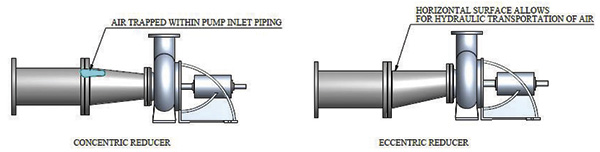 Figure 1. Difference between eccentric and concentric reducers in pump inlet piping (Article graphics courtesy of the authors.)
Design guidelines, pump operating manuals and design standards mostly prescribe the selection of an eccentric reducer with the flat side on top for horizontal flow to the pump. This configuration prevents air pocket accumulation at the upstream end of the reducer (see Figure 1). The non-uniform velocity distribution results from the acceleration of flow along the eccentric reducer’s sloped side resulting in an unbalanced force that is not addressed. An unbalanced force on the impeller could lead to potentially detrimental radial thrust harmonics.
Abstract from the Design Standards
ANSI/HI 9.6.6 American National Standard for Pump Piping for Rotodynamic Pumps (P4, 2009) specifies the following for the selection of reducer type in pump inlet piping: “A concentric reducer is recommended for vertical inlet (suction) pipes or horizontal installations where there is no potential for air vapor accumulation.
Eccentric convergent reducers are normally used for horizontal installations where there is potential for air vapor accumulation. The flat side shall be located on top, unless the inlet (suction) line approach from above, in which case either a concentric reducer or eccentric convergent reducer (with the flat side on the bottom) should be used.”
ANSI/HI 9.8 American National Standard for Pump Intake Design (P21, 1998) states, “There shall be no flow disturbing fittings (such as partially open valves, tees, short radius elbows, etc.) closer than five suction pipe diameters from the pump. Fully open, non-flow disturbing valves, vaned elbows and reducers are not considered flow disturbing fittings.”
This standard eliminates any reference to the possible flow distribution that could be generated by the reducer. This standard (P28, 1998) also requires that, “Time-averaged velocities at the pump suction in a piping system shall be within 10 percent of the cross-sectional area’s average velocity.”
This requirement can be used to assess the extent of flow disturbance caused by a reducer. ANSI/HI 9.8 also recommends a maximum flow velocity of 2.4 meters per second (m/s) in the suction pipe work.
ANSI/AWWA C208 American Water Works Association Standard – Dimensions for Fabricated Steel Water Pipe Fittings (P7, 2008) directs the length of a reducer (Lr) to be calculated with the following formula.
Equation 1
Lr = 4 (DL – Ds)
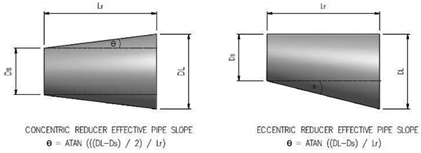 Figure 2. Calculation of reducer angles
Where:
Lr = Length of the reducer
DL = Larger pipe diameter
Ds = Smaller pipe diameter
The reducer angles for the ANSI/AWWA C208 were calculated with the method in Figure 2 to compare it to the requirements in Table 1. The calculated angles are:
- ANSI/AWWA C208 Eccentric Reducer Angle = 14.04°
- ANSI/AWWA C208 Concentric Reducer Angle = 7.13°
The minimum number of straight pipe lengths required is determined by the number of pipe reductions, regardless of the reducer angle staying constant. For a single pipe reduction, the standard ANSI/AWWA C208 reducer has no requirement for downstream pipe lengths before the pump.
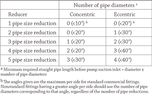 Table 1. Minimum straight length required before suction inlet
In the second part of this series, the recommendations presented in ANSI/HI 9.6.6 will be assessed using computational fluid dynamics and compared to the ANSI/HI 9.8 and ANSI/AWWA C208 requirements.
References
- ANSI/AWWA C208-07. 2008. Dimensions for fabricated steel water pipe fittings. American Water Works Association, Denver.
- ANSI/HI 9.8-1998. 2000. American National Standard for pump intake design. Hydraulic Institute, New Jersey.
- ANSI/HI 9.6.6-2009. 2009. American National Standard for rotodynamic pumps for pump piping. Hydraulic Institute, New Jersey.
- VAN VUUREN, S.J., VAN DIJK, M and STEENKAMP, J.N. 2004. Guidelines for effective de aeration. WRC Report No. 1177/2/04. Water Research Commission, Pretoria.