


Q. What principles drive the pumping action in a controlled-volume metering pump?
A. The pumping action is developed by a reciprocating piston. This reciprocating motion develops a flow profile represented by a sine wave. Actual rate of flow is determined by the following formula:
Rate of flow = Displacement x
Cycles per unit of time x Volumetric efficiency
Figure 7.3.1a illustrates how changes in discharge pressure minimally affect the rate of flow from a reciprocating, controlled-volume metering pump.
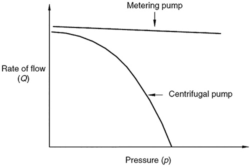 Figure 7.3.1a. Rate of low versus pressure (Graphics courtesy of Hydraulic Institute)
Figure 7.3.1c shows the rate of flow versus stroke-length setting for a controlled-volume metering pump at a given pressure and stroking speed. The curve is linear, and it is not necessarily proportional. The 50 percent stroke setting may not equal 50 percent flow, because the curve may not pass through zero on both axes simultaneously. Other rates of flow versus stroke length settings can be accurately predicted by measuring flow at two rate-of-flow settings, plotting both points and drawing a straight line through them.
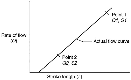 Figure 7.3.1c. Actual flow curve, rate of flow versus stroke length
The relationship between the theoretical and actual rate of flow of a controlled-volume metering pump is illustrated in Figure 7.3.1d. The difference between the theoretical and actual curves represents the volumetric efficiency (VE), the ratio of the actual pump delivery per stroke to theoretical displacement, expressed as a percent.
For more information on controlled-volume metering pumps, see ANSI/HI 7.1-7.5
Controlled-Volume Metering Pumps for Nomenclature, Definitions, Application and Operation.
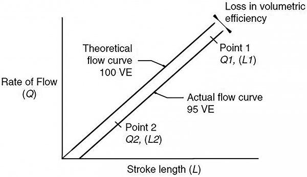 Figure 7.3.1d. Theoretical and actual flow curve,rate of flow versus stroke length
Q. What are the advantages of dual seals, and how are they subcategorized?
A. Dual seals include more than one set of sealing surfaces. Dual seals typically require the use of an external liquid or gas and are operated with an auxiliary system. They require more auxiliary systems and monitoring than a single seal. The total initial cost is usually higher and requires the installer to have additional training. The benefits are increased reliability and safety.
Dual seals are used when one or more of the following criteria cannot be achieved by using a single seal design:
- Emission control of process fluid to the environment under normal operating conditions
- Emission of process fluid under upset conditions or failure of the primary seal
- Acceptable life (time between repairs) as a result of inadequate lubricating properties of the pumped medium, which may be a result of too many solids too close to vapor pressure, too low viscosity in combination with pressure and speed, or too high pressure differential for one set of faces
The advantages of dual seals include:
- Dual pressurized seals can seal products that crystallize, burn or are otherwise unsuitable for single seals.
- Dual seals can limit loss to the atmosphere. This feature may be a factor in seal selection for equipment handling hazardous materials.
- Seal life may be improved as the seal faces operate in a clean, cool environment.
- Seal performance can be confirmed by monitoring the barrier fluid.
Dual seals are subcategorized as dual pressurized and dual unpressurized. In a dual pressurized seal, the external fluid is at a higher pressure than the seal chamber pressure. As a result, all faces of the mechanical seal are lubricated. In this design, the external liquid is called a barrier fluid. In the dual unpressurized seal, the external fluid is at a lower pressure or, as in most applications, at ambient pressure. The external fluid is called a buffer fluid. Dual seals come in several configurations and with a variety of application-specific design features. Their faces can be arranged face-to-back, face-to-face and back-to-back.
The advantages of the pressurized dual seals over the unpressurized versions are:
- The faces are lubricated using a clean, cool liquid—usually oil, water or glycol—which provides low wear rates.
- Dual gas seal faces are separated with a clear inert gas such as nitrogen.
- The seal operates independently from the pump. Consequently, loss of product, cavitations or other disturbances can be better tolerated.
- Zero emissions or product leakages are released into the atmosphere.
For more information on mechanical seals, see the HI Guidebook Mechanical Seals for Pumps: Application Guidelines.
Q. What pump component casting properties are affected by variations in test tolerances, and how can an increased level of precision be obtained?
A. Various manufacturing processes often dictate the level of precision possible in the production of a certain part. A large percentage of pump components are produced as cast parts that must be subsequently machined, cleaned, dressed and assembled into stationary and rotating assemblies prior to the pump test. Normal manufacturing variations can have an impact on the continuity of hydraulic geometry and, therefore, affect performance.
Casting dimensional variations depend on the molding process. Low-volume, large components are frequently molded in sand using manual processes. As with most manual processes, an inherent large variation exists in the process, both dimensionally and in the resulting surface finish. Machine molding is used on higher production volume components and results in less variation in dimensions and finishes. For a higher level of precision, some components may be cast using an investment process that results in the smallest variation in both dimensions and finishes.
The variation of hydraulic surface finish of the casing or impeller is different for the various types of cores used to make the part. Wax cores exhibit little variation in finish and typically do not cause hydraulic performance variations. Sand cores, particularly those that are hand-molded, can have significant variation in surface finish. Variation in molten metal temperatures can also result in variations in surface finish in a single foundry run. The surface finish in these types of cores can affect head and efficiency.
Minor variations in the contour of the leading edge of impeller vanes can affect the net positive suction head required (NPSHR) significantly. Because leading edges are often thin, they can be easily deformed. Casting shrink rates are affected by chemical composition variations within alloy specifications, pouring temperature and cooling rates. The resulting dimensional variations affect head and efficiency.
Casting cleaning is the process in which a raw casting is manually or automatically cleaned and dressed. Casting burrs, surface imperfections and mold split lines are often ground off and smoothened out. Hydraulic passageways are often dressed and matched by hand. These processes result in variations of the local geometry of the part. An increased level of precision can be obtained through the introduction of more sophisticated metal removal processes and metrology.
For more information on test tolerances, see ANSI/HI 14.6 Rotodynamic Pumps for Hydraulic Performance Acceptance Tests.