


Q. When selecting wetted pump parts, how much consideration should be given to the temperature of the pumped liquid?
A. Handling liquids at temperatures below 32 F (0 C) or above 250 F (120 C) requires careful selection of the materials and corresponding attention to construction details. Many materials’ corrosion resistance or physical properties are affected by high or low temperatures.
When selecting materials for temperature ranges, consult the applicable codes and practices of the industry in which the pump will be used. Pump material for low-temperature operations should be selected only after each component and its function have been considered. Many materials change from tough to brittle in cold temperatures.
To start, when selecting a suitable ferric steel for low-temperature service, the user may consider a heat-treated, fine-grain, low-carbon alloy steel with low phosphorus, nickel and molybdenum, and of moderate hardness. This offers better notch toughness at low temperatures.
Consideration should also be given to the austenitic stainless steels and bronzes for possible use in low-temperature pumping applications. Austenitic stainless steels, fully annealed, show improving toughness with decreasing temperature and exhibit no transition point. Most bronzes and all aluminum alloys are not embrittled at low temperatures and may also serve for this type service, if otherwise suitable for the application.
Other considerations—cost, corrosion resistance, availability, erosion resistance, hardness, toughness and fatigue strength—must also be considered before final selection is made. It should also be noted that other factors should be considered when selecting materials for wetted pump parts—such as the user’s experience, the manufacturer’s experience, the expected pump life (such as temporary or long-term use), intermittent or continuous duty, pumping hazardous or toxic liquids, and the condition of the liquid.
Q. What is a foot valve, and in what pumping application would one be used?
A. Foot valves are specially designed check valves used at the inlet of the suction lift line to maintain pump prime, by maintaining liquid over the first-stage impeller (see Figure E.1). They are designed to open with little pressure differential across the valve.
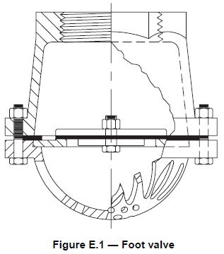
They should be installed in a vertical orientation (or they may not work), below the top of the waterline, and the end of the inlet (suction) line should be at least four pipe diameters below the top of the water level. This will maintain a primed condition in the inlet line. The foot valve and pipe should be sized to minimize inlet line losses that will maximize the net positive suction head available (NPSHA) to the pump.
Leakage and failure to close problems may be encountered if solids are present in the liquid. Therefore, foot valves may be limited to pump installations in which pump nonperformance due to foot valve failure does not place the user at high risk. End users should note that, unless a suction pressure relief is fitted, pumps must have the suction side designed to contain the maximum allowable working pressure of the pump, plus any hydraulic shock loading or water hammer due to sudden foot valve closing.
In vertical pumps, foot valves may be used at the inlet of the bowl assemblies for well pumps to keep the column pipe filled, to prevent backspin and to prevent well disturbance from rapidly draining water. This practice is limited and occasionally used on small, less than 5-horsepower (3.7-kilowatt) pumps, with less than 100-foot (30-meter) settings and 50-psig (345-kPa) surface pressure. The user is encouraged to check with the vertical turbine manufacturer for warranty ramifications when using foot valves.
Q. What are some differences between simplex and duplex air-operated pumps?
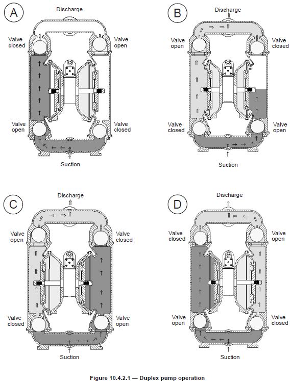
A. For a duplex air-operated pump, compressed air is directed into the air chamber via the air distribution system. The compressed air is separated from the liquid by a diaphragm. The diaphragm applies pressure on the liquid and forces it out of the pump discharge. While this happens, the opposite-side air chamber is depressurized and exhausted to the atmosphere and liquid is drawn into the pump suction. The cycle repeats, creating a reciprocating action (see Figure 10.4.2.1).
A simplex pump operates in much the same way, but no liquid is discharged during the recharge stroke. A spring return is used to return the diaphragm and provide energy for the suction stroke. Intake and discharge valves direct flow into and out of the pumping chamber. Also, simplex pumps require a controller to cycle the compressed air/gas into the air chamber of the pump and to exhaust the air. The controller can be mechanical or electrical. The speed of the pump is set by the controller, and the maximum speed is determined by the manufacturer.
To determine the maximum pumping speed on a duplex pump, increase the air supply while the pump rate of flow increases. When rate of flow no longer increases, throttle back the air supply until the pump rate of flow starts to decrease. This point is the optimum pump cycle rate achievable under the system conditions.