


A typical metering pump application in water treatment, chemical process or agriculture can deliver large amounts of chemicals during daily operations. While the volumes may be large, the metering also must be precise, with exact amounts delivered according to strict injection schedules. The wide range of injection pressures, from high to low, must also be governed precisely. These demanding applications require the use of a unique pumping technology, one that can ensure successful, reliable adherence to the injection schedule and fluid volumes.
Metering pumps have become a top choice for the injection of chemicals in water treatment, processing and agricultural applications. Many styles and modes of operation are available, so users must understand the different metering pump technologies in order to select the ideal equipment for their injection applications.
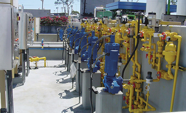 Image 1. Metering pump users must consider many factors when designing a system (Images courtesy of Neptune Chemical Pump Company)
Know The Parameters
When determining which metering pump is the best option for a chemical injection application, users must consider several variables:
- Flow rate. Metering pumps should never be oversized, so determining the exact flow rate required for the application is paramount. A metering pump should be sized so that the maximum expected flow rate is 85 to 90 percent of the pump's capacity.
- Materials of construction. Metering pumps are available in a variety of materials, most commonly 316 stainless steel, C-20 stainless steel, PVC and Kynar polyvinylidene fluoride (PVDF). Users must consider the corrosion, erosion and solvent action of the chemical. For example, solvent-based chemicals may dissolve plastic-headed pumps, while acids and caustics may require stainless-steel models. The effects of erosion must also be considered with abrasive slurries.
- Chemical makeup. Chemicals come in many formulations, from thin to highly viscous, and they can also be classified as a slurry or off-gas when transferred. Standard metering pumps are typically able to handle clear liquids with viscosities ranging from water-like to 1,500 centipoise (cPs). Chemicals with viscosities that approach 5,000 cPs or have light suspensions will require special liquid ends. Those with viscosities up to 20,000 cPs or that contain up to 10 percent solids will require special diaphragms, while ones that automatically vent accumulated gas will need their own type of liquid ends.
- Driver. Drivers—which can be powered by electricity, water, gas, air or the sun—must be selected according to the utilities that are available. Users must also consider any environmental hazards that may be found in the operating area, with the operator realizing that pumps used in remote locations may not be able to be inspected as often as those in controlled environments.
- Environment. Determine if the pump will be operating indoors or outdoors. If used outdoors, the pump must be sheltered from direct sunlight. Any pumps that will be used in freezing temperatures can only pump fluids that will not freeze at that temperature.
- Method of control. The operator must know if the pump will be used in manual continuous operation, on/off operation or operation that is governed by a process signal.
Method of control is arguably the most important variable when choosing a metering pump. Many styles of metering pumps allow their flow rates to be adjusted manually through the use of a micrometer dial. Adjusting this dial changes the pump's stroke length and allows the pump to be operated anywhere between 10 and 100 percent of its rated flow capacity. Metering pumps with micrometer dials may also feature a variable speed drive that allows adjustment of the pump's stroke speed. Using the two in unison can allow additional flexibility or turndown capabilities, over the range of the drive, depending on the pump's stroking speed.
Flow rate set-point can be maintained automatically by using electric or pneumatic positioners to adjust the stroke length, which will deliver a full 10-to-1 turndown ratio. In this method, the number of doses remains constant with the size of each dose reduced, resulting in doses that are uniformly distributed in a constantly flowing line.
Metering pumps that use a variable speed drive will deliver a turndown ratio that is determined by dividing the pump's stroke speed by its minimum operating speed. A variable speed drive will enable the pump to inject a dose of the same size on each stroke, but because the stroke speeds will change, the doses themselves will be less frequent. Additionally, using a variable speed drive with an induction motor-driven pump, which normally operate at speeds less than 100 to 150 strokes per minute (spm), is not practical because slowing the motor causes each stroke to take longer to complete. However, electronic metering pumps, which are pulsed by a solenoid, can operate at less than one spm because the timing of each stroke, from start to finish, is uniform at every stroking speed.
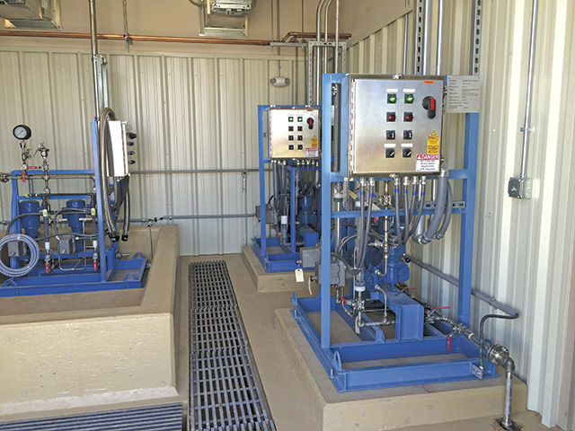 Image 2. Method of control is arguable the most important variable when choosing a metering pump.
Metering Pump Installation
When designing a pumping system, users must consider any existing location or environmental concerns. Keep in mind that metering pumps are able to "push" against high pressures but will struggle to "pull" over longer distances.
This means that suction lift should be limited to no more than 4 feet and that a foot valve should be used in top-mount installations. Flooded suction is always preferred in a metering pump installation to ensure the pump is easier to prime, but the length of the flooded suction should be limited to 6 or 7 feet. Other components of the installation to consider include:
- Suction piping. The traditional rule of thumb is to use pipe that is one size larger than the pump's suction connection, though using pipe that is the same size as the suction connection is acceptable, if the metering pump will be operating at a slow speed when transferring low-viscosity chemicals. Generally, do not use hard piping that is smaller than 3/4-inch in diameter or that is smaller than 3/8 inch in diameter for low-flow applications that use plastic tubing.
- Discharge piping. The size of discharge pipe is not as critical as that of the suction pipe, but the piping must be suitable for the discharge pressure. Typically, matching the pipe size to the discharge connection should be sufficient.
- Suction strainer. A suction strainer should always be used, because it prevents foreign matter from entering the pump's ball checks.
- Flanges/unions/compression fittings. At least one of these fittings must be installed at the suction and discharge ports to facilitate maintenance procedures.
- Isolation valves. Large-port, quick-opening isolation valves should be placed at both the suction and discharge ends of the installation as a way to ease maintenance operations. Needle valves should not be used because their design will create flow restriction.
- Calibration column. Because metering pumps often feature pulsed flow at low volumes, a draw-down calibration column is the most accurate and convenient method to measure pump performance. A tall, thin column should be used to ensure ease of reading and reporting accuracy. Calibration columns can also be helpful in determining if any wear has occurred or dirt has accumulated in the pump's check valves. If the liquid in the column "bounces," that may indicate that the valves are worn or dirty.
- Relief valve. Though the metering pump may be constructed with an internal relief valve, users should consider installing an external relief valve. It should be set at 50 psi (3.5 bar) or 10 percent above the maximum operating pressure, whichever is greater. Any chemical that flows through the relief valve is piped back to the feed tank. Using transparent tubing for the relief valve will allow the operator to observe any returned fluid and identify any impurities. When piping the relief valve's return to the suction side of the installation, the return must be upstream of the pump's isolation valve so that the flow rate will not become blocked.
- Back-pressure valve. This component is only necessary when the installation does not produce adequate back pressure and the pump does not contain a built-in back-pressure device. Back-pressure valves are also required when a system has a low-pressure injection point that is hydraulically lower than the feed tank.
- Pressure gauge. The pressure gauge should be sized 30 to 50 percent larger than the maximum expected pressure that is produced by the system.
- Pulsation dampener. Pulsation dampeners are most commonly required in systems that feature long discharge lines where fluid acceleration can adversely affect the pump's maximum pressure capacity or relief valve setting. The pulsation dampener will minimize the pressure spikes that these acceleration circumstances may cause.
- Injection quills/check valves. An injection quill that is installed at the pump's injection point will serve as a check valve while providing better dispersion of the chemical. In low-pressure applications, an injection quill that incorporates a corporation stop, which allows the injection quill to be inserted or removed without having to drain or shutdown the system, will improve efficiency and overall performance.