


A fact of life is that equipment operators spend more time with pumps than mechanics do. Leveraging this familiarity with equipment, operator-driven reliability (ODR) programs focus on maximizing plant reliability by enhancing the techniques operators use to monitor the equipment for which they are responsible. ODR is not a new concept, and many companies around the world have deployed ODR programs to various levels of success. One benefit of ODR is the ability to improve seal mean time between failures (MTBF).
The first step toward improved seal MTBF through ODR is understanding why a seal fails. It is often for reasons other than reaching the end of its life span, such as lubrication problems, vibration or installation errors.
During their routine rounds, operators are often asked to document only if the seal is leaking and if the seal pot level is acceptable. While this may seem reasonable, plant management may not be getting value from the tasks they have asked the operator to perform.
For example, the operator can log that the seal is leaking, but does he or she know enough about the different seal flush plans used in their area to identify where the leak is coming from? Is the leak coming from between the shaft and the seal sleeve, between the seal sleeve and the seal gland, the seal gland and the head, or from a leaking piece of tubing, piping or union? Depending on the source, the operator may have an opportunity to mitigate the leak before creating a work order that could lead to costly misdirected pump maintenance.
If the operator only has the option to answer yes or no to whether the seal pot level is in the acceptable range, plant management can miss critical information. In many cases, knowing if the seal pot level is low, normal or high could be a sign of a primary seal face leak, a secondary seal face leak or even a seal flush cooler leak, depending on the specific seal flush plan.
Some equipment—such as coolers, purges, vent lines, quenches, reservoirs and collection vessels—is often ignored during inspection. To ensure that operators are monitoring the seal flush system properly, plant management should optimize inspection techniques, provide training on the new techniques with visual aides both in the control room and in the field, and provide operators with the right tools to properly execute the inspections.
Suggested Tasks for Operators to Improve Seal MTBF
Because some leaks can be mitigated without maintenance, operators should routinely monitor seals for leakage and identify the source of the leaks.
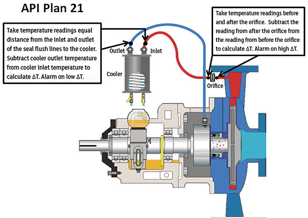 Figure 1. API Plan 21 (Graphics courtesy of Schneider Electric)
They should periodically monitor seal flush line temperatures before and after the orifice(s) found on many American Petroleum Institute (API) Plan 11, 13, 14 and 21 seals and calculate the change in temperature (∆T). An increasing ∆T is a sign that the flush line is starting to plug. An infrared (IR) temperature gun is typically needed to complete this task. Plant management should mark and label the locations at which operators will take temperature readings. Ideally, the locations should be painted flat black to reduce the likelihood of bad readings caused by emissivity.
Operators should also periodically monitor the seal flush line at the inlet and the outlet to the cooler found on many API Plan 21, 23, 41, 52, 53A and 53C seals and calculate a ∆T (see Figure 1, page 45). A decreasing ∆T is a sign that the cooler may be starting to foul. Check to make sure cooling water lines are properly lined up, and, if possible, back flush the cooler while the pump is online. In some cases, it may be necessary to shut down the pump to back flush the cooler. This task generally requires an IR temperature gun. Seal flush inlet and outlet lines to the cooler should be properly labeled, marked and painted flat black.
Periodically monitor seal flush line temperatures before and after the cyclone separator found on many API Plan 31 and 41 seals and calculate a ∆T. An increasing ∆T is a sign that the flush line is starting to plug and the cyclone separator should either be cleaned or replaced. An IR temperature gun is the best tool for this task if temperature gauges are not installed on the seal flush piping. Seal flush inlet and outlet lines to the cyclone separator will need to be properly labeled, marked and painted flat black.
Routinely verify that the flush line is totally iced over on API Plan 31 seals when in butane or propane service.
Routinely monitor seal flush flow and pressure indicators on API Plan 32 seals. Knowing the actual stuffing box pressure allows personnel to accurately set the safe operating range.
Monitor seal flush control system valves routinely to ensure proper position and that the strainer is not plugged on API Plan 32 seals.
Routinely monitor buffer/barrier fluid level in the fluid reservoir on API Plan 52, 53A, 53C, 54 and 55 seals. Level changes indicate different problems based on the seal flush plan used. A level change often indicates primary or secondary seal face leakage.
Monitor vent line pressure on API Plan 52 seals routinely. Increased pressure is an indication of primary seal face leakage. The vent line valve should be open.
Routinely monitor barrier system pressure on API Plan 53A, 53B, 53C and 54 seals. Knowing the actual stuffing box pressure is important for accurately setting the safe operating range of the barrier system pressure, which can help maintain isolation of product from the atmosphere.
Periodically monitor accumulator pre-charge pressure on API Plan 53B seals. As the pressure decreases, add more barrier fluid to increase system pressure back to an acceptable range. If possible, record the amount of barrier fluid that was added so that leakage rates can be calculated.
Routinely monitor quench pressure and valve positioning on API Plan 62 seals. Quench pressure should never exceed the maximum design limit.
If steam is used as the quench method, operators should also monitor the condition of the steam trap.
Routinely monitor the drain valve position and the overflow chamber level indicator on API Plan 65A and 65B seals. A high level in the overflow chamber may indicate excessive seal leakage.
If heat tracing is installed, ensure that tracing is working during required periods. Operators will need to drain the collection vessel on API Plan 65B seals when the vessel level indicator approaches full.
Routinely monitor the pressure indicator on API Plan 66A and 66B seals to detect excessive leak rates. These are typically monitored by pressure transmitters and may not require manual inspection.
On API Plan 66B seals, operators should monitor the drain line temperature to ensure that the drain orifice is not plugged.
Routinely monitor vent line pressure, buffer gas pressure and buffer gas flow on API Plan 72 seals (see Figure 2, page 47). Pressure in the vent line is an indication of primary seal face leakage. Buffer gas pressure should always be lower than seal chamber pressure. Flow should be regulated to ensure that proper cooling is supplied to the seal faces.
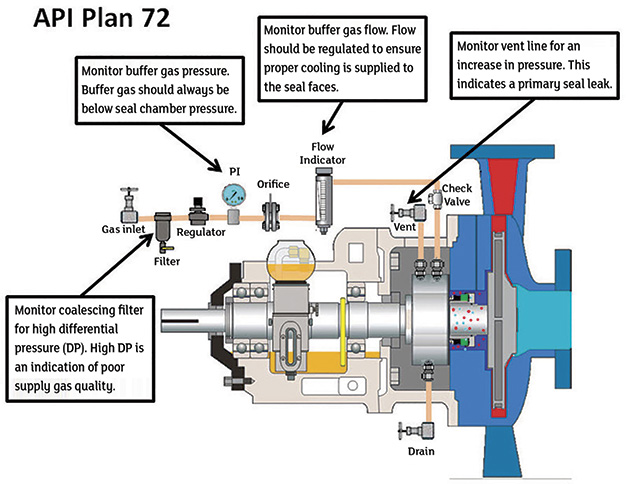 Figure 2. API Plan 72
Routinely monitor barrier gas pressure and flow on API Plan 74 seals. The barrier gas pressure must be higher than seal chamber pressure at all times. Barrier gas flow could indicate primary or secondary seal face leakage. If flow is present, ensure that the upset drain is not leaking.
Periodically monitor the coalescing filter on API Plan 72 and 74 seals for high differential pressure. If the gas supply quality is poor, the coalescing filter will become plugged over time.
Routinely monitor the vent pressure, valve positioning and collection reservoir level (API Plan 75 only) on API Plan 75 and 76 seals.
Increased vent pressure is an indication of primary seal face leakage. The collection reservoir should be drained to a liquid collection system as needed.
On-Site Implementation
These tasks are only suggestions, but plant managers should remember that a properly designed and maintained seal can last for more than 10 years. Field inspections of seal flush systems depend greatly on the field installations themselves and on each site’s readiness to embrace ODR methodologies.
In many cases, successful ODR implementation will require a change of the existing plant culture, adequate training programs and an introduction of new technologies for operators to use to effectively execute the designated tasks. Commonly used technologies include mobile workforce and decision support software applications, ruggedized mobile computers and peripheral devices such as IR temperature guns.