


Magnetic bearing systems represent a different approach from rolling bearings to support rotating machinery, and in recent years, their benefits have attracted attention for more applications.
As a non-contacting technology, magnetic bearings will exhibit negligible friction loss and no wear. They can attain high speeds with undetectable vibration and are valued for their energy-efficient performance and savings in applications ranging from vacuum pumps to gas and air compressors.
For example, a 12,000 rpm, 12 MW centrifugal compressor at a natural gas pipeline facility in upstate New York was fitted with magnetic bearings instead of traditional, hydrodynamic bearings. This switch to a system that consumes a fraction of the energy (because it rotates without contact) yielded documented annual energy savings of 700,000 kWh and an overall 88 percent energy saving for the compressor system (encompassing compressor and motor). In addition, an auxiliary oil lubrication system, cooling system, gearbox (variable, high-speed motor directly coupled to the compressor), and condition monitoring equipment were eliminated, which reduced the footprint of the machinery and the number of potential failure points.
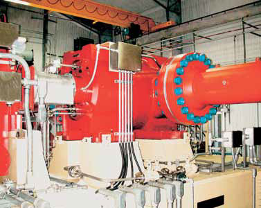
Centrifugal compressor fitted with magnetic bearings
While, depending on the application, the advantages of magnetic bearing technology compared with the oil film technology it replaces will vary in importance, the following features and benefits will often be cited:
- Reduced wear. In normal operation, the rotating portion of the machinery is not in contact with any parts. Reduced wear decreases maintenance requirements and operating costs.
- Increased efficiency. Virtually no shaft energy is consumed by bearing friction. More power goes directly into the process and enhanced efficiency follows.
- “Green” operation. Without lubrication oil, concerns about potential leakage, accidental loss and disposal become irrelevant.
- Programmable characteristics. Depending on the application or process variables, the physical response of the bearing can be adjusted “on the fly.” In some cases, this means that a shaft can safely pass through critical vibration speeds and operate at speeds that were previously unattainable.
For all the advantages, the technology is not without some limitations. Magnetic bearings tend to be physically larger than similarly specified bearing systems. Also, by necessity, magnetic bearings require electric power to drive the control systems, sensors and electromagnets.
Incorporating Distinct Technologies
An active magnetic bearing system consists of several distinct technologies: electromagnet bearing actuators, position sensors, control system and power amplifiers. The bearing actuators and sensors will be located in the machine, and the control system and amplifiers usually will be located remotely.
Magnetic bearings provide attractive electromagnetic suspension between the rotor and stator by applying electric current to ferromagnetic materials used in the stationary parts (the stator) of the magnetic bearing. This creates a flux path through both components and levitates the rotor, creating the air gap separating them. (The air gap between the stator and the rotor will usually be 0.5 mm to 2 mm and makes the non-contact operation possible.)
As the air gap between these two parts decreases, the attractive forces from the magnets increase. Since electromagnets are, in this way, inherently unstable, a control system is necessary to constantly adjust the strength of the magnets by changing the current and provide stability of the position of the rotor.
The control process begins by measuring the rotor position with a position sensor. The signal from this device is received by the control electronics, which compares it to the desired position established during machine start-up. Any difference between these two signals results in a calculation of the force necessary to pull the rotor back to the desired position. This is translated into a command to the power amplifier connected to the magnetic bearing stator. The current is increased, causing an increase in magnetic flux, an increase in the forces between the rotating and stationary components, and movement of the rotor toward the stator along the axis of control.
The entire process is repeated thousands of times per second, enabling precise control of machinery rotating with peripheral speeds of up to 200 m/s. A closer look at each of the system components follows.
Radial and Thrust Bearings
A typical system incorporates two radial bearings and a thrust (or axial) bearing. Each radial bearing has a stator and sensor system mounted over a ferromagnetic rotor installed on the shaft. The rotor consists of a stack of lamination rings mounted on a sleeve that fits onto the shaft. (Laminations are designed to reduce eddy current losses and improve the response of the bearing.) The stator includes a stack of lamination rings with poles on the internal diameter. Coils are wound around each pole to divide the bearing into four quadrants. The coils in each quadrant are wound in series to make each quadrant function as one electromagnet. Typically on horizontal machines, the quadrants are aligned 45 deg from vertical. Opposing quadrants constitute an axis (each radial bearing, then, can be described by two axes). A set of sensors to measure shaft position is mounted as close to the bearing as possible.
The thrust (or axial) bearing typically consists of two stators, one on either side of a rotor disk as well as a position sensor to indicate the rotors axial position. The stators are made either of solid steel or solid steel wedges with radial slots between the wedges filled with laminations to improve the response of the bearing. The thrust stators also have one or two circumferential slots machined into the face and filled with coils. With a stator mounted on each side of the rotor, the thrust bearing can counteract axial forces in both directions.
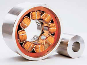
Radial Bearing
Control System
The control system utilizes the signals from the position sensor to determine the position of the shaft. This signal is compared to a reference to determine the error in the position. After appropriate conditioning, this signal is sent to power amplifiers that control the current sent to the bearings.
In simple terms, the control system reduces the upper bearing current when the shaft is above the center position and increases the current when the shaft is below the center position.
Magnetic bearing control normally will be performed in a single input/single output (SISO) manner. This means that the position information from one sensor causes only the control current in the corresponding axis to be varied. (Control systems can also be multi-input and multi-output, or MIMO. MIMO is used when higher levels of control are required or when significant cross-coupling between axes is expected.)
The components of the control system include position sensors and electronics, controller, and amplifiers. Sensors relay information about the position of the shaft to the controller in the form of an electrical voltage. Normally, the sensors are calibrated so that when the shaft is in the desired position, the sensor produces a null voltage. When the shaft is moved above this desired position, a positive voltage is produced, and when it is moved below, a negative voltage results.
The controller receives the voltage signal from the position sensors, processes the information and sends current requests to the amplifiers. The controller consists of anti-aliasing filters, analog-to-digital (A/D) converters, a digital signal processor (DSP) and pulse-width modulation (PWM) generators.
The voltage from the position sensors is passed through the anti-aliasing filters to eliminate high-frequency noise from the signal. (This noise can cause the signal to inaccurately represent the position of the shaft.) After the high-frequency content is removed, the position signal is sampled by the A/D converter. This converts the voltage signal to a form that can be processed by the DSP and the digital information is passed through a digital filter by the DSP. This produces an output proportional to the amount of current required to correct the position error in the shaft.
The requested current is compared to the actual current in the bearing, which is also sensed, filtered and sampled with an A/D converter. The error between the actual and requested current is used to characterize the PWM signal that is sent to the amplifiers. This information is forwarded to the PWM generators, which create the PWM wave form sent to the amplifiers.
Each bearing axis has a pair of amplifiers to provide current to the bearing coils and provide an attractive force to correct the position of the rotor along that specific axis. The amplifiers are high-voltage switches that are turned on and off at a high frequency, as commanded by the PWM signal from the controller.
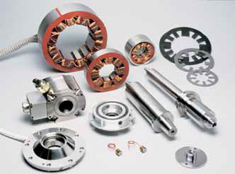
Centrifugal compressor fitted with magnetic bearing components
When to Consider the Technology
Magnetic bearings can both complement and contribute to applications in which particular conditions will be experienced or where specific performance requirements must be met. Some appropriate applications follow.
Clean Environments
A magnetic bearing system will not contaminate a clean process with oil, grease or solid particles.
High-Speed Applications
Because a rotor in a magnetic bearing system spins in space without making contact with the stator, drag on the rotor is minimal. This allows the bearing to run at exceptionally high speeds. The only limitation to speed will be the yield strength of the rotor material. The positive outcome is that no other type of bearing can match magnetic bearings for sheer speed. Magnetic bearings have been designed with surface speeds up to 250 m/s. To achieve a fraction of this speed, conventional bearings would require a complex lubrication system.
Position and Vibration Control
Since magnetic bearings use advanced control algorithms to influence the motion of the shaft, they precisely control the position of the shaft within microns and eliminate most vibration.
Extreme Conditions
A magnetic bearing system can operate over a wide temperature range—as low as -256 deg C and as high as 220 deg C—temperatures at which traditional bearings cannot function. Systems can additionally operate in corrosive environments, are not sensitive to pressure, can be submerged in process fluid under pressure without requiring seals and can operate in a vacuum.
Machine Diagnostics
This capability can take three forms: online machine analysis, stimulus/response diagnostics and static clearance checking. The hardware integrated into the bearing system (instead of expensive add-on equipment) can continuously monitor, while online, changes in machine vibration against predetermined limits as an indication of machine or process anomalies.
In cases of excessive load, the system can signal process control equipment to stop the machine instantaneously before serious damage can occur. Besides controlling and minimizing vibration in a shaft, an active magnetic bearing system can perform diagnostics by exciting the shaft with controlled wave forms and frequencies, either while the machine is idle or running.
During operation with conventional bearings, process errors may overload the bearing system, which forces an operator to restart a potentially damaged machine or take the machine off-line for inspection. (This usually involves dismantling a portion of the machine, accruing associated maintenance costs, and losing productivity.) A magnetic bearing system can mitigate these issues with the capability to move the shaft within its clearance limits and indicate any changes caused by effects such as thermal distortion or metal deformation.
Conclusion
The evolution of sophisticated software control systems and the unique inherent characteristics of magnetic bearings have advanced the technology as a practical solution for an increasing number of applications. In fact, failure modes of magnetic bearings tend to be limited to the control electronics, power electronics, and electrical windings, and even in these modes, magnetic bearings provide performance and reliability levels that make magnetic bearings an attractive choice for many critical applications.
Pumps & Systems, October 2010