


A thrust bearing can run hot for many reasons—such as excessive load and/or speed, inadequate oil supply or an axial clearance that is too tight. Typically, the reason a thrust bearing runs hot is because, for whatever reason, the load has increased. Time could be spent trying to address the root cause of the problem (the increased load, and indeed that task should be undertaken in parallel) or a redesigned bearing could be installed to address the symptom (a hot running bearing). This article discusses design options available to reduce thrust bearing operating temperatures. First, assume the existing bearing was designed, manufactured and installed correctly, is operating at the correct speed and has an adequate lube oil supply. The assumed reason for the excessive temperature is that the bearing is being subjected to a higher than anticipated load, and thrust load is one of the few measurements that are not usually verified.
Common design options to increase the load capacity of a thrust bearing that fits into the same envelope—so no other modifications are required—include:
- Upgrade from steel-backed pads to copper alloy-backed pads
- Modify to an offset pivot design
- Upgrade to a direct lubricated design
Of course, these design changes presume that the bearing does not already incorporate them, and they can be combined to maximize the upgrade potential. Each of these will be addressed separately.
Upgrade from Steel-Backed Pads to Copper Alloy-Backed Pads
API specifications have stated that thrust bearings be “steel-backed.” This dates back to early editions, and the reason for this may be that a given bearing’s load capacity could be easily improved by upgrading from steel-backed pads to copper-backed pads. This upgrade could be performed by having drop-in copper pads manufactured and ready when the machine is brought down—then a simple pad swap could be performed (the float and rotor position should be checked and may need adjustment).
Copper-backed pads also fit into the “yellow metals” category. In the past, there were concerns that contaminated oil may attack the copper. Today, most lube systems are relatively clean and process products being entrained in the oil is not an issue. This is further reinforced by the thousands of bearings installed with copper alloy pads. Some extreme pressure (EP) oil additive packages contain sulfur (active or inactive), and sulfur may interact with the copper. The copper has no direct load applied to it (no contact stresses), so damage to the copper from sulfur attack, if it even occurs, is trivial. American Society for Testing and Materials (ASTM) test D130 could be considered if there is an EP package and a concern of attack.
The copper backing used is actually a copper alloy that is 99 percent copper and 1 percent chrome. The chrome significantly adds to the strength and stiffness of the pad. One issue with copper is that it has an affinity for tin, and when bearings are babbitted, a layer of tin is applied between the base metal and the babbitt (and the babbitt is a high-tin material itself). This concern is addressed by applying a barrier layer to the copper prior to the tinning operation. This layer isolates the copper from the tin and eliminates the problem. Copper is used because of its high heat transfer characteristics. It is about 450 percent more heat conductive than steel and this conductivity pulls heat from the babbitt surface, reducing the pad temperature. Figure 1 is a plot of the maximum pad temperature versus the bearing load for a given set of conditions (such as speed and oil supply). For this plot, only the pad material was changed.
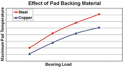 Figure 1. Maximum pad temperature versus bearing load—pad material changed
At the low load condition, the drop in pad temperature is half that of the higher load. This is because the hotter the bearing runs, the more effective the use of copper will be—taking maximum advantage of the copper’s increase in thermal conductivity compared to steel. Reductions in temperature of 25 F (14 C) are not uncommon for hot running bearings.
Modify to an Offset Pivot Design
Most tilting pad thrust bearings are supplied with pivots centered in the pad circumferential direction. This is referred to as a 50-percent offset in which the offset is measured from the pad’s leading edge. By using a 50-percent offset, the active and inactive bearings (which experience an opposite direction of rotation) can be identical.
By moving the pivot downstream circumferentially (from the leading edge), the pad is encouraged to tilt, opening the leading edge and allowing more oil into the area between the pad and the thrust collar. This increase in pad flow cools the bearing. To a point, the more the offset, the more effective the benefit. Depending on the specific bearing configuration, some bearing modifications (other than just pad modifications) may be required to upgrade to an offset pivot design.
End users may be concerned that a machine running backward when using offset pivots can damage the bearing. This is a valid concern if the machine is designed to operate in both directions at full speed and load. However, in most process machines, reverse rotation is designed against and normally occurs when a machine is shut down and the process fluid flows backward through the machine. In most instances when this occurs, the load and speed are a fraction of the design load and speed of the machine. Offset pivot pads can be operated backward, but their load capacity is compromised—the more the pivot offset, the more the load capacity in reverse is reduced. A quick review of reverse operation potential is warranted when upgrading from center pivot pads to pads with an offset pivot.
Figure 2 is a plot of the maximum pad temperature versus the bearing load for a given set of conditions. For this plot, only the pivot offset was changed.
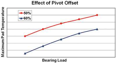 Figure 2. Maximum pad temperature versus bearing load—pivot offset changed
The benefit of the offset is realized equally throughout the load range since it is a function of pad oil flow. Here, as much as a 40 F (22 C) drop in temperature is possible.
Upgrade to a Direct Lubricated Design
Conventional “catalog” tiling pad thrust bearings are designed to run flooded in a bath of oil. This is accomplished by admitting oil to the bore of the bearing and allowing it to discharge out the top of the housing, with seals at the shaft under the bearings to keep the oil from leaking. The problem is that all the oil in the housing is subjected to the rotation of the shaft and thrust collar. This results in a churning loss which manifests itself as a parasitic power loss and elevated temperatures entering the leading edge of the thrust pads. This is referred to as a flooded design.
By upgrading to an evacuated design, the total bearing power loss can be reduced and the bearing maximum operating temperatures can be lowered. To make sure the oil enters the leading edge of the pad, a directed lubrication scheme is customarily used. This can either be some sort of spray bar or nozzle arrangement or a groove or pocket ahead of the pad that is supplied with oil. All these configurations can be referred to as a directed lubrication design.
Typically, direct lubricated thrust bearings run evacuated by allowing the oil to leave the bearing housing as soon as it exits the pad. For an upgrade project, this would require modifications to the bearing housing (adding large drain holes at the bottom of the housing at the collar outer diameter).
A concern in this situation is that, if the bearing is not flooded with oil and there is a loss of oil, no reserved oil is available to save the bearing. In fact, the thrust collar in these arrangements acts as a surprisingly efficient centrifugal pump and even flooded bearings run dry shortly after the loss of oil because of the pumping action of the collar. Figure 3 is a plot of maximum pad temperature versus bearing load for a given set of conditions. For this plot, only the lubrication scheme was changed. Again, the benefit of running evacuated is realized equally throughout the load range since it is a function of oil churning at a given speed and oil flow rate, so the oil heating will remain constant. Reductions in pad temperatures of up to 10 F (6 C) are possible with an upgrade of this type.
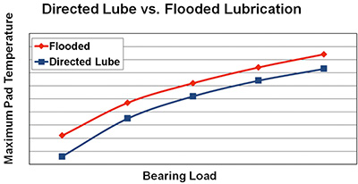 Figure 3. Maximum pad temperature versus bearing load—lubrication scheme changed
Conclusion
Three techniques to lower the operating temperature of hot running, tilting-pad thrust bearings were presented. While maximum benefit could be achieved by using all three methods, the amount of benefit potential is not cumulative. Consult with the original equipment manufacturer or bearing vendor for an analysis of a given situation. Advanced analysis tools can be used to predict the reduction in temperature possible for each specific case.
References
- Gardner, W. W., “Performance Tests on Six-Inch Tilting Pad Thrust Bearings,” Transactions of the ASME, Journal of Lubrication Technology, pp. 430 – 438 (1975).
- New, N. H., “Experimental Comparison of Flooded, Directed, and Inlet Orifice Type of Lubrication for a Tilting Pad Thrust Bearing,” Transactions of the ASME, Journal of Lubrication Technology, pp. 22 – 26 (1974).
- Whalen, J. K., “Thrust Bearing Analysis, Optimization and Case Studies,” Proceedings of the 25th Turbomachinery Symposium, pp. 17 – 24 (1996). P&S