


Enable the sealless transition with ceramic-matrix composites.
Sealless pumps, such as magnetic-driven and canned-motor pumps, are becoming more common in the petrochemical and power industries for their enhanced reliability and reduced leakage. Traditionally, pump manufacturers used SiC (silicon carbide) for bushings and bearings in these pumps because of its high hardness and ability to withstand abrasive wear in solid media.
Since the early 1980s, OEM pump manufacturers have been using sintered SiC bearings for the stationary and rotating components of tubular casing pumps. While SiC has been the preferred bearing material over other alternatives such as carbon, its vulnerability to thermal and mechanical shock can cause fractures. Due to the material's high hardness, the splintered pieces of fractured bearing can lead to a catastrophic pump failure—resulting in significant process disruption and downtime.
New technologies and processing techniques have been developed to bring a new ceramic-matrix composite (CMC) material to the market—enabling the transition to sealless pumps with bushings and bearings that virtually eliminate catastrophic failure in magnetic-driven and canned-motor pumps with superior fracture resistance over traditional silicon carbide components. It is the material properties of these composites that deliver improved mean time between failures (MTBF), reduced maintenance costs and increased safety.
Material Characterization
CMCs consist of a ceramic matrix reinforced by either continuous fibers, short fibers, whiskers and/or particles. These reinforcements are designed to improve the fracture toughness of conventional ceramics, which are inherently brittle materials. A number of fabrication techniques—such as chemical vapor or liquid phase infiltration and the standard hot pressing and sintering techniques—are available. One available CMC material is produced by a chemical vapor infiltration process in which crystalline silicon carbide is deposited on and between SiC fibers by process gasses. The major disadvantage of this CMC material is the long process times due to the slow growth of the SiC that translates into a high-cost material.
A new CMC material is processed using a multi-step infiltration and pyrolysis process. The resulting microstructure of this CMC after this process is shown in a cross-sectional view in Figure 1 with the dark regions (A) showing the carbon fibers included to prevent crack propagation for improved impact and thermal shock resistance, while the lightest grey regions (B) are SiC particles included to enhance the stability of the composite and improve its wear resistance. These particles also reduce the shrinkage of the overall matrix during densification, which improves the process-ability. The remaining medium-grey area (C) is the SiC matrix that binds the overall composite together.

Figure 1. Scanning electron microscope cross-sectional view of the new CMC material, (A) carbon fiber, (B) SiC particles, (C) SiC matrix
Thermal Shock Resistance
To compare the thermal shock resistance of this new material to SiC, the upper temperature limit of the CMC was initially determined through thermogravimetric analysis (TGA). This was conducted on the CMC material in air up to 1,000 degrees C at a ramp rate of 10 degrees C per minute as shown in Figure 2. At 600 degrees C, the new CMC begins to lose considerable weight due to the oxidation of the carbon fibers.
[[{"type":"media","view_mode":"media_original","fid":"8024","attributes":{"alt":"","class":"media-image","height":"350","typeof":"foaf:Image","width":"527"}}]]
Figure 2. Plot of the thermogravimetric analysis of the new CMC material in air
The thermal shock resistance was determined by measuring the change in flexural strength by rapidly quenching test specimens in a room temperature water bath according to ASTM C 1525-04. Flexural bars were made out of the new CMC and sintered SiC.
The flexural strength was measured at room temperature on as-machined, baseline test bars and on bars heated and quenched in room temperature water. The flexural strength as a function of temperature is shown in Figure 3. Each data point is an average of 10 specimens.The flexural strength of the sintered SiC shows essentially no change from the room temperature baseline up to 400 degrees C. However, at 500 degrees C the flexural bars fractured upon quenching them in the water bath and therefore, could not be measured. In comparison, the new material's flexural strength did not show this drastic reduction, as the test bars remained intact after quenching at all the temperatures. The flexural strength changed from approximately 160 MPa on the room temperature baseline to 60 MPa at 600 degrees C.
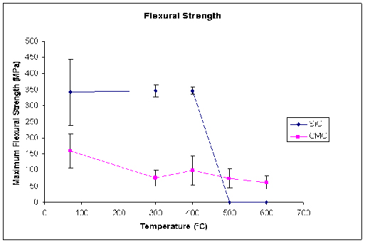
Figure 3. Change in flexural strength as a function of temperature for the new CMC and sintered SiC
Coefficient of Thermal Expansion
The coefficient of thermal expansion (CTE) measurements were made on the new material bearings using a custom dilatometer system as shown in Figure 4, which is based on ASTM E-228-06. The linear variable differential transducers were positioned to measure the displacement of the outer diameter, thickness and length as the temperature was ramped from 22 degrees C to 600 degrees C at an average rate of 3 degrees C per minute. The dimensions of the bearings made from the new CMC were approximately 105 millimeters (outer diameter), 54 millimeters (inner diameter) and 51 millimeters long.
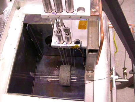 Figure 4. Custom dilatometer system designed to measure the coefficient of thermal expansion of the bearings made from the new CMC material
The results of an average CTE over the range from 22 degrees C to 600 degrees C on three bearings are:
Outer diameter CTE = 0.8 x 10-06/ degrees C
Inner diameter CTE = -2.0 x 10-06/ degrees C
Length CTE = 1.4 x 10-06/ degrees C
As the temperature increases, the outer diameter, and length expand, while the inner diameter contracts. This unique behavior is consistent with the anisotropic property of carbon fibers. The CTE of carbon fibers parallel to the fiber direction is negative, while the CTE perpendicular to the carbon fiber is dominated by the SiC matrix.
Chemical Corrosion Resistance
The corrosion resistance of this new CMC was evaluated by immersing specimens in concentrated acids and bases in sealed Parr bombs at temperatures up to 100 degrees C for 200 hours. The changes in the weight of specimens were measured and expressed as milligrams per square centimeter of exposed surface. The selection and concentration level of each of these chemicals was previously reported in a design guide to sealless magnetic drive pumps.
The results of these corrosion tests compared to sintered and reaction-bonded SiC are shown in Figure 5. There is very little weight change in the CMC specimens after immersion in strongly acidic solutions. The new material is vulnerable to erosion by concentrated HF, particularly in an oxidizing environment, and by strong alkalis.
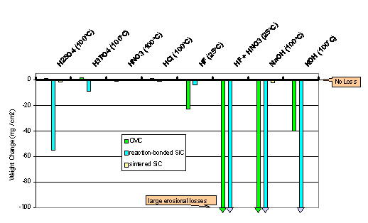
Figure 5. A plot showing the chemical compatibility tests on the new CMC in comparison to reaction-bonded and sintered SiC
Tribological Friction and Wear Tests
Water lubricated sliding wear tests were performed according to a modified version of ASTM D 3702-94 to simulate sleeve bearings in magnetic drive pumps. The test specimens are shown in Figure 6, where a disc specimen made of the new material rotated against a stationary specimen made out of either sintered SiC or 1018 hardened steel. The test procedure involved increasing the speed of the rotating specimen in steps up to 900 rpm and then back to zero at a specified normal load. The specimens were immersed in water that was maintained at an ambient temperature, and the friction coefficient was continuously monitored and plotted against the rotational speed.
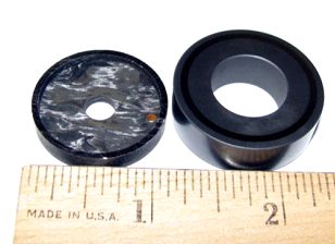
Figure 6. Picture of the wear test coupons, the new CMC material is on the left and the SiC stationary specimen on the right
A series of tests were conducted on the new material sliding against 1018 hardened steel at different normal load as shown in Figure 7. The friction coefficient exhibited a steady behavior over the entire speed range as the normal load was increased from 35.5 N to 285 N, indicating elastohydrodynamic lubrication (EHL) conditions. However, at the 445 N normal load, the friction coefficient becomes unstable as the water film breaks down into a boundary lubricated EHL regime. At the 890 N normal load, the friction coefficient becomes unstable and the test was terminated due to excessive friction on the steel coupon.
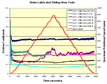
Figure 7. Water lubricated sliding wear test results on the new material against steel for various loads over a range of rotational speeds
To understand the effect of a harder counterface material, the new CMC material coupons were tested against sintered SiC at the 890 N normal load. As shown in Figure 8, the friction coefficient exhibits a stable value considerably less than 0.1 over the entire speed range. The tribological pair of the new CMC/SiC remains in a lubricated EHL regime even with low viscosity liquids, such as water at high contact stresses.
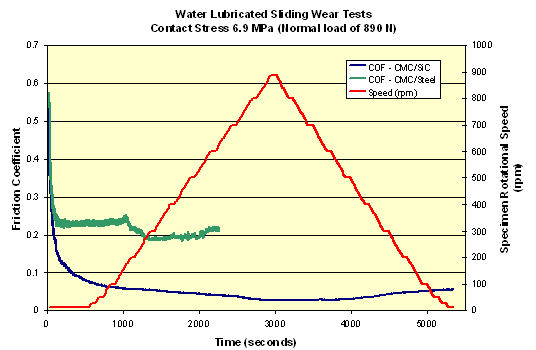
Figure 8. Water-lubricated sliding wear test results on the the new material against sintered SiC and steel at 890 N normal load over a range of rotational speeds
The 890 N normal load wear scar on the stationary specimens was measured with an optical profilometer. It was observed that the CMC rotating specimen caused considerable wear on the steel specimen as shown in Figure 9. The depth of the wear scar is approximately 23 µm, while in the case of the sintered SiC, the worn region is two orders of magnitude less, approximately 0.24 µm, as shown in Figure 10. These results indicate that the new CMC material should be run against a material that is similar in hardness, particularly when the pumping medium is a low viscosity fluid such as hydrocarbons, acids, solvents, etc.
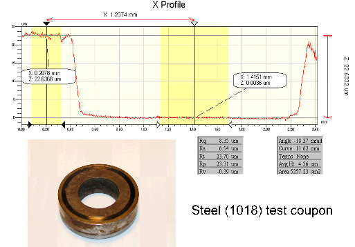
Figure 9. Surface profilometer trace across the wear scar on the stationary steel specimen after the 890 N normal load test
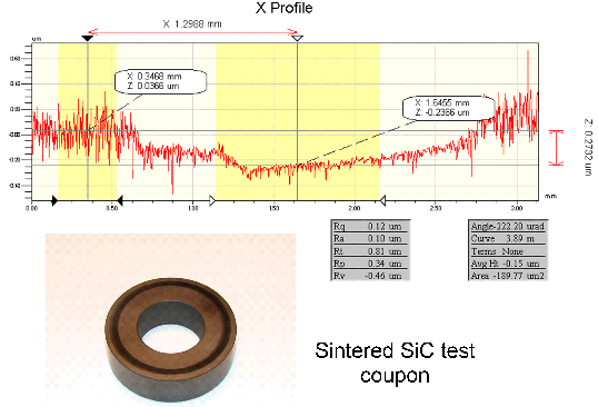
Figure 10. Surface profilometer trace across the wear scar on the stationary sintered SiC specimen after the 890 N normal load test
A Better Way to Go Sealless
This new CMC material is enabling the transition to sealless pumps for petrochemical and power companies. It leverages carbon-fiber reinforcement with a proprietary processing technology to achieve superior impact resistance and thermal shock capabilities—eliminating catastrophic failures caused by failed bearings.
This material delivers exceptional operational performance in sealless pumps with improved fracture and wear resistance over current bearing materials. Developed with a specialized processing technology, it delivers design flexibility for bushing and bearing solutions with better impact resistance and thermal shock capabilities. It is capable of withstanding temperatures over 1,100 degrees F (600 degrees C) and provides enhanced dry running capabilities over existing bearing materials.
Pumps & Systems, September 2011