


Explore differential pressure, electromagnetic, vortex and swirl, and variable area (rotameters).
Engineers tend to specify volumetric flowmeters to measure liquids when they simply require a measure of the volume of flow per unit of time (gallons/minute, liters/sec, etc.). When corrected for temperature or density, volumetric flowmeters can provide values for mass liquid flow rates. A sampling of volumetric flowmeters includes differential pressure, electromagnetic, vortex and swirl, and variable area (rotameters). Excluded here for reasons of space are turbine, target, ultrasonic and positive displacement meters.
A primary criterion for flowmeter selection is accuracy. Flowmeter accuracy often depends to some degree on application conditions. Pressure, temperature, fluid dynamic influences and external influences can all affect accuracy. Pressure and temperature cause dimensional and physical changes. Fluid flow profiles and pipe roughness can shift flowmeter performance. In other words, a traceable and complete calibration in a lab is no guarantee that a user can expect the same performance and accuracy in the field.
Another significant flowmeter attribute is rangeability, often called turndown ratio. This is the ratio of the maximum to the minimum flow rate capable of being measured at a specified accuracy. In processing industries, extremely high values of rangeability are often meaningless because most processing flow velocities fall within relatively narrow ranges. Liquid pipeline flow rates, for example, typically range from 0.5 to 12 ft/sec, a turndown ratio of 24:1. Accuracy usually falls off for lower flow rates when flow becomes laminar rather than turbulent. Higher flow rates generate high pressure drops, raising pumping energy costs and causing pipe erosion (if solids are present).
Differential Pressure Flowmeters
DP flowmeters are a popular choice in the processing industries, comprisingnearly 30 percent of installations. These flowmeters consist of two components: some element inserted into the flow to increase its velocity and a sensor/transmitter to measure the unrecoverable differential pressure that results. The inserted element is typically an orifice plate, Venturi, nozzle or wedge. The measured differential pressure is a square root function of the volumetric flow rate.
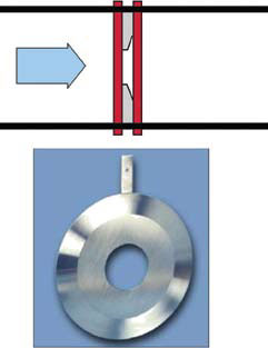
Orifice Plate
These flowmeters have no moving parts, can result in moderate pressure losses and suit extreme temperatures and pressures. Accuracy ranges from 1 to 5 percent. Compensation techniques can improve accuracy to 0.5 to 1.5 percent. Disadvantages include:
- Expensive to install and maintain
- Nonlinear function of flow rate
- DP transmitter required to compute volumetric flow
- Limited rangeability (often less than 5:1)
- Sensitive to changes in temperature, density and viscosity
Characteristics of the inserted elements vary. The orifice plate is the most common, being greatly studied, inexpensive and available in a variety of materials. Rangeability is usually less than 5:1. Accuracy tends to be 2 to 4 percent of full scale. Retaining good accuracy requires maintaining a sharp edge to the upstream side of the orifice plate, which degrades with wear. Pressure loss is high relative to other DP elements.
The Venturi flowmeter is primarily used in water and wastewater applications. Since pressure loss is minimal, it is a good choice when only minimal pressure head is available. It handles dirty fluids and does not require upstream flow profiling (although the Venturi itself has a relatively long length). Rangeability is less than 6:1 and accuracy runs from ± 1 to 2 percent of full scale. Viscosity greatly affects accuracy and flow must be turbulent (Reynolds numbers greater than 10,000).
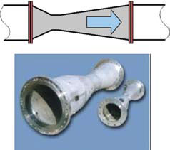
Venturi
Nozzles, while acting somewhat like Venturis, tend to be shorter for fitting in tighter piping situations. They come in a variety of configurations, some standard and some proprietary, often requiring dependence on manufacturer's data.
The wedge consists of a V-shaped restriction molded into the meter body. In profile the wedge looks like a segmental orifice plate to the incoming fluid, but it is more expensive than an orifice plate. This basic meter has been on the market for more than 40 years, demonstrating its ability to handle tough, dirty fluids. The slanted faces of the wedge provide self-scouring action and minimize damage from impact with secondary phases. Rangeability of 8:1 is relatively high for a DP element and accuracies are possible to ± 0.5 percent of full scale.
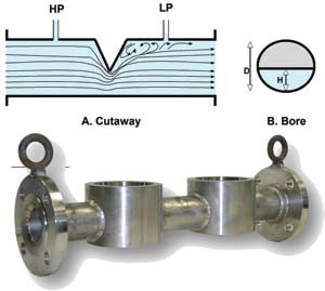
Wedge
For especially abrasive or corrosive liquids, the wedge flowmeter can come with remote seals that effectively isolate the metered fluid from the tubes running to the DP transmitter.
Electromagnetic Flowmeters
Often called magmeters, these flowmeters are also a popular choice among instrument engineers, making up about 20 percent of flowmeter installations. Faraday's law says that a conductor moving through a magnetic field produces an electric signal. In this case, the fluid is the conductor and electromagnetic coils surrounding the meter body generate the magnetic field.
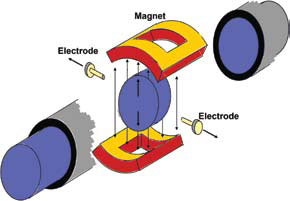
Magmeter
Magmeters have no moving parts. They offer high accuracies and wide rangeability as well as an unobstructed flow path. They are ideal for slurries, and perform well with corrosive and erosive fluids. Engineers can pick a non-conductive liner material for the flow tube-Teflon, Tefzel, rubbers, ceramic-to suit the fluid measured. Magmeters require minimum lengths of straight pipe to condition the flow profile. The fluid measured must be conductive, however, which rules out most petroleum-based flows.
The voltage developed across the electrodes within the flow tube is in the millivolt range and should be carried via shielded cable to a nearby converter. The converter boosts the signal to a standard (4-20 mA) or frequency output (0-10,000 Hz) for transmission to a display or controller.
The coils producing the magnetic field may be excited by AC, DC or pulsed DC. DC excitation accounts for most magmeter installations today.
Line frequency AC designs offer fast response to changing flow rates and good signal-to-noise ratios. They tend to be susceptible to zero drift, however, and require frequent manual adjustment of the output at zero flow. Recent advancements to AC designs, along with sophisticated digital signal processing techniques, have incorporated ways to minimize or eliminate zero drift.
With pulsed DC excitation designs, a low frequency DC pulse (about 7 Hz) excites the magnetic coils. The converter reads both the flow and noise signals during an "on" pulse. In between pulses, however, it sees only noise, permitting noise cancellation after each cycle. Zero drift is not a problem for pulsed DC designs. The downside tends to be low signal-to-noise ratios and long response times caused by signal conditioning.
Vortex/Swirl Flowmeters
Place a blunt obstacle within a fluid pipeline, and the fluid will alternately produce whirling vortices on either side of it. The spacing between the vortices remains constant, regardless of the fluid velocity. Piezoelectric or capacitance sensors typically count the pressure oscillations caused by the vortices. The vortex shedding frequency provides a measure of fluid velocity.
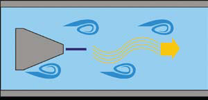
Vortex
Like a vortex meter, swirl meters detect pressure pulsations whose frequency depends on the flow rate. Vanes in the meter cause the incoming fluid to take the shape of a rotating helical coil of alternating pressure zones. At low flow rates, the low pressure swirls or coils are far apart. As flow rates increase, the coils become compressed, coming closer together. Detectors within the meter measure the frequency of the swirling low pressure zones as they pass through the meter. A deswirler at the meter's exit eliminates any effects on downstream instruments.
Applications should avoid dirty, corrosive or abrasive fluids. The meters have no moving parts, have wide rangeability and are immune to pressure, temperature or density changes. They lose effectiveness, however, as viscosity increases. They are also affected by vibration or pulsation.
Swirlmeters are less sensitive to flow profiles than vortex meters. While vortex meters may require a minimum or 15 or more upstream and five downstream straight pipe diameters, swirl meters require only three and one, respectively. Both may be installed horizontally or vertically, but must be kept full of fluid during operation. About half of all vortex meter installations require necking down oversized process piping by concentric reducers and expanders.
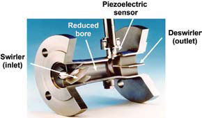
Swirl meter cutaway
Variable Area Meters
Commonly known as rotameters, these devices provide practical solutions for many flow metering applications. They are simple and inexpensive, performing as well or better than many high-tech flowmeters on the market.
Every rotameter basically consists of two components: a tapered metering tube made of glass, metal or plastic and a float that rides within the tube. These components come in a wide variety of shapes, sizes, weights and materials of construction, making them adaptable to a wide range of application needs. They are easy to install and maintain, but must be mounted vertically and plumb. Some designs can handle high pressures and viscosities. Today, most manufacturers have taken all the factors and data involved in sizing a rotameter and incorporated them in a sophisticated software program.
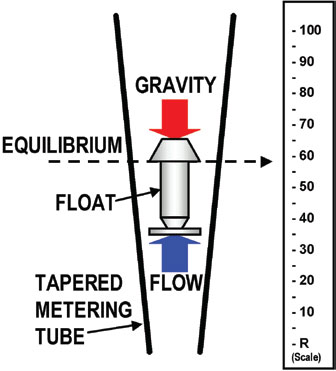
Rotameter
Accuracy, however, is relatively low (±2 percent) and depends on precise knowledge of the fluid and process. Rotameters are susceptible to vibration and plugging by solids, and are affected by density and temperature changes. They apply primarily to flow rates below 200 gpm and pipe sizes less than 3 in.
Selection Chart
Table 1 provides selection information based on the nature of the liquid to be measured. It can be used as a rough guide, but the specifics of an application will narrow the selection further or suggest exceptions.
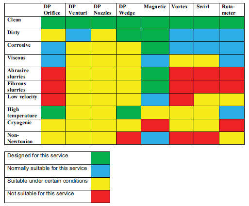
Table 1. Volumetric flowmeter selection chart for liquids
Pumps and Systems, July 2010