


VFDs replace mechanical devices and PLCs for lead-lag pump control.
When a pump is started and run across the line, it will provide maximum flow at optimal efficiency. However, a pump motor operated continuously at full rated speed is inefficient during periods when maximum flow is not required, and the pump and motor will wear out faster than if the pump speed were regulated.
The affinity laws—which express the relationship between a pump's shaft speed, volumetric flow rate and power—state that running a pump at rated speed generates rated flow at rated power. However, a pump motor powered directly from the line will still be running near full power during periods of reduced demand. Operating in this way is inefficient, especially if the pump is oversized to accommodate future demand. One method of designing a better pumping system is to use lead-lag control.
Lead-lag control is nothing new in the pumping industry, and a common lead-lag design features a duplex booster pump system to maintain building water pressure. In these designs, lead-lag control is used so that a system that requires multiple pumps to maintain water pressure at peak demand will not have to use all the pumps when the demand is reduced or nonexistent.
Preferably, some of the pumps can be shut down when demand is low, and the system can be designed so that the water pressure can be maintained by a single pump during periods of low demand. Properly designed lead-lag systems will improve the efficiency, performance and longevity of the pumping system.
VFDs Beat Mechanical Control
A lead-lag system requires that the pump controls switch the pump motors on and off based on demand. The simplest way to switch the motors on and off is with an across-the-line starter in the form of a contactor. However, starting a motor directly across the line at full power presents issues. Powering a motor directly across the line will result in high starting currents. The current draw from a line started motor can be in excess of six to seven times the motor's full load amperage rating. This not only stresses the motor, but can result in excess demand charges from the electric utility.
Across-the-line starters can be used in combination with other mechanical devices to regulate the pump's output—including balancing valves, ball valves and butterfly valves. Some of these devices will require manual adjustments, while others are designed to automatically control pressure. These mechanical devices can reduce pressure to desired levels but do not solve the across-the-line starting issue nor significantly contribute to energy savings.
A better approach for maintaining the desired water pressure is to regulate the speed of the pump motor with a variable frequency drive (VFD). VFDs control the speed of AC induction motors by controlling the frequency and voltage supplied to the motor. While mechanical devices can be installed at a pump's output to adjust flow, a VFD regulates flow by adjusting the motor/pump speed. This approach is much better for a number of reasons:
- Uses a minimum amount of energy
- Reduces motor starting current
- Provides a degree of motor protection
- Cuts the wear and tear on the motor
- Simplifies the design of the flow control system
- Provides extensive diagnostics
- Reduces the required maintenance
When a VFD is used, the controlled motor's efficiency is optimized and runs at maximum efficiency regardless of the required flow and corresponding motor/pump speed. The VFD input current rises linearly with respect to output power because the VFD can slowly ramp the pump up to speed. As a result, the typical six to seven times motor rated current seen with an across-the-line started motor is nonexistent with a VFD.
As a result, the negative impact of frequent start/stop cycles is greatly reduced because the VFD limits the motor's inrush current, which and prevents the motor's thermal rises that are inherent with across-the-line starting.
Basic VFDs provide phase loss detection and motor thermal overload protection. Advanced pump-specific VFDs offer features such as loss of prime detection, detection of a pump in a no-flow (deadhead) condition, low/high-pressure level detection, broken pipe protection and pump over cycle protection. These factors make VFDs superior to mechanical devices for regulating pump flow, and other features of VFDs allow direct implementation in complex pump control applications.
Integrated PID Control Is Better Than External PLCs
(Moved later in the paragraph) Many VFDs have a built-in proportional-integral-derivative (PID) loop controller, which makes external PID controls unnecessary. These External controls are typically implemented with a programmable logic controller (PLC) or a stand-alone proportional-integral-derivative (PID) controller. In either case, an extra component must may need to be purchased, programmed, installed and interfaced to the VFD. However, many VFDs have a built-in proportional-integral-derivative (PID) loop controller, which makes external PID controls unnecessary. Performing PID and other control functions internal to the VFD saves money, reduces complexity and cuts installation effort. The advantages of this setup are:
- Costs less
- Simpler to configure
- Reduces integration among control components
- Requires less space
- Requires less maintenance
In pump control applications, the VFD's built-in PID feature is used to continuously monitor a feedback signal to maintain an output set point by adjusting motor/pump speed. In the case of a system used to maintain water pressure in a building, the VFD automatically increases the motor's speed and the pump's output as the feedback signal shows a drop in pressure.
Conversely, the VFD reduces motor/pump speed and eventually shuts the system down based on pump flow requirements as determined by the feedback from the pressure sensor. As a result, the VFD controls the motor/pump to generate the required flow to maintain the demanded pressure, all without the need for additional external automation components.
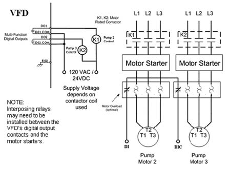
Figure 1. VFD with across-the-line lag motors and pumps
Using VFDs to Implement a Lead-Lag System
A single VFD can be used in a basic lead-lag system to regulate pressure by directly controlling the lead pump motor's speed, while turning the lag booster pumps on and off through each pump's across-the-line starter (See Figure 1). This scheme uses the VFD's discrete outputs (dry output relays) to control each booster pump's motor contactor.
Typically, the VFD activates the lag pumps one at a time when the demanded pressure can no longer be maintained by the active system. Eventually, the VFD-controlled lead pump and the lag pumps all run simultaneously to provide full flow to meet the system's peak demand requirements.
The VFD regulates water pressure as demand fluctuates, and the input power required by the pumping system is minimized. Simply put, the VFD will monitor the pressure and draw just enough power to ensure that the system maintains demand. In addition, the VFD will reduce the speed of the lead motor as each lag pump motor is activated, reducing stress imposed on the system due to water hammer and further increasing efficiency.
Inversely, the VFD will shut off each lag sequentially as the system requires less flow to maintain demand. As each backup pump shuts off, the VFD will adjust the speed of the lead motor to maintain the demanded flow. This will occur until the lead motor/pump is solely responsible for meeting demand. Ultimately the demand may diminish enough so that the pump will barely be creating flow. At this point, the VFD can be programmed to shut the motor/pump off, essentially putting the system to sleep until demand increases.
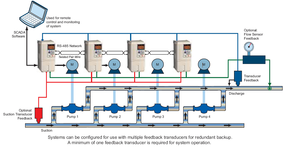
Figure 2. Four VFD multiplex pump system
Multiplexing VFDs
Multiplexing allows multiple VFDs to operate as a coordinated system, and it requires a high level of automation. If this automation is to be implemented via VFDs alone as opposed to VFD/PLC combos, advanced pump-specific VFDs are required. All the VFDs must be able to communicate over a digital network, and each VFD must be able to provide the required pump logic and PID control.
In the example shown in Figure 2, the multiplex pump system uses a transducer to sense line pressure. This transducer sends an analog 4-20mA signal proportional to pressure to one of the VFDs. Communications among the VFDs is via a simple Modbus RS-485 digital network in this example, although many networks are available to accomplish the required communications including Ethernet-based networks such as Ethernet/IP.
Required control and sequencing is configured through the VFDs, with communications among the VFDs via the digital network. The single pressure feedback signal is re-transmitted among the VFDs over the network, so only one feedback device is required no matter how many VFD/pump combinations are used.
However, multiplex systems typically use at least two feedback sensors configured in a redundant mode in case one sensor fails. Upon losing the primary feedback signal, the VFD will automatically switch to the other feedback signal, while simultaneously alerting the operator of the primary feedback signal's failure. As a result, the pump system will experience no interruptions.
Another level of redundancy is built into each of these pump-specific VFDs. If a VFD is currently running a pump and loses power or shuts off, the other idle VFDs will automatically come online as required to maintain system demand.
Advanced pump specific VFDs can be configured to operate in different ways in a multiplex system. In the Figure 2 example, when the lead VFD cannot maintain the demand of the system, it activates the lag units through the digital network. When this occurs, the most recently activated VFD becomes the lead and regulates its output frequency based on the feedback signal, while the former lead unit becomes a lag unit running at a fixed preset speed.
An alternate configuration would allow all the VFDs to regulate motor/pump speed based on the pressure feedback signal, ensuring that the pumps share the load equally. In typical operating conditions, this would result in all the motor/pumps running at the same speed. This would balance pump, motor and VFD wear and tear.
With this alternate configuration, as the demand decreases the running pumps will shut down one by one until a single pump is left running. If demand continues to reduce, the final pump can be configured to shut off.
Some advanced pump-specific VFDs have the capability of alternating which unit starts as the lead VFD based on lowest total run time, ensuring that each VFD/motor/pump will accumulate a roughly equivalent run time. Some pump-specific VFDs can also be configured to accommodate systems where a jockey or pressure maintenance is used to maintain the desired pressure in low demand conditions. More complex pump control capabilities available in some VFDs include pressure control using a secondary feedback for water level monitoring and regulation, suction level monitoring and/or regulation water level or suction pressure control and flow level monitoring.
Like a PLC—advanced VFDs can be programmed, monitored and maintained with PC-based software. Unlike a PLC, this software is generally provided free by the VFD supplier. VFD programming and monitoring software is also easier to use than similar software for PLCs because the software is for a single application specific rather than general purpose.
VFDs have been used to control pumps for many years. However, advanced pump-specific VFDs now allow users to improve motor/pump control and protection without the need for inefficient mechanical devices or costly PLCs.
Pumps & Systems, October 2011