


A flexible coupling's primary functions are connecting two shafts, transmitting power from a driver shaft to a driven shaft and accommodating the misalignment between them. With only these requirements, it would appear the coupling selection could be narrowed down to one or two types. Unfortunately, it is not that easy. All flexible couplings accomplish the above three functions, but they do so with varying degrees and attributes. It is within these secondary coupling attributes that the best coupling selection is separated from the fair, poor or even disastrous ones. No single type of coupling will be perfect for all applications.
In industrial pump applications, both lubricated and non-lubricated couplings are used. Some common coupling options include disc, shear jaw and bonded tire non-lubricated designs, as well as grid and gear style lubricated couplings.
Coupling Attribute Comparison
In the selection process, coupling manufacturers help users make selections based on general requirements such as torque, speed shaft sizes and shaft gap. To select the best coupling for an application, the requirements of the application must be reconciled with the performance attributes of the specific coupling. Although there are many attributes to consider for the five couplings mentioned, we will compare the following coupling attributes-misalignment, speed, torsional stiffness, weight, torque density, temperature and generated thrust forces-for a 100 hp, 1,750 rpm centrifugal pump with a 5 in shaft gap between the motor and the pump.
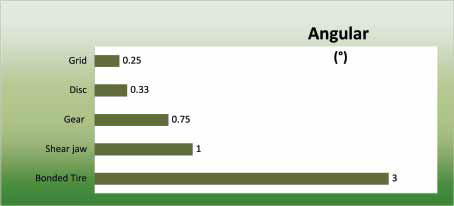
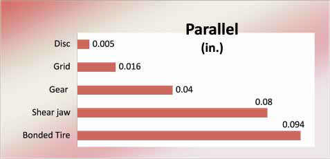
Misalignment
For purposes of our discussion, the misalignment levels referenced here are operational limits, which are the maximum levels of misalignment the coupling can accommodate before experiencing shortened life (see Figures 1A, 1B and 1C).
 |
 |
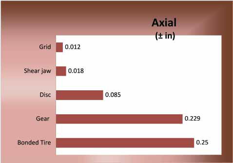 |
Figure 1A (top), Figure 1B (middle), Figure 1C (bottom)
In addition, coupling manufacturers are typically able to provide installation limits, which are lower misalignment values than operational limits. Aligning equipment at or below the installation limits will help reduce equipment vibration and extend the life of other system components like bearings and seals. It is important to remember that using a high misalignment coupling such as an elastomeric one to compensate for misalignment is no excuse for poor alignment practices. Although the coupling may be able to tolerate the misalignment, other components of the pump system may not fare as well.
Axial misalignment, although often overlooked, can be important where thermal growth is an issue or where sleeve bearing motors, herringbone gearsets and other axially sensitive equipment is involved. Gear and tire-type elastomeric couplings have relatively high axial misalignment capacity, but axial forces may result from this movement. Thrust forces will occur in tire-type elastomeric couplings as a result of axially stretching or compressing the elastomeric element. In the case of gear couplings, this effect may result from forces required to slide the coupling under load.
Speed
Where high coupling speed ratings are required, a disc or gear coupling is the best choice due to compact size and inherently balanced designs. In addition to the relatively high speed ratings of the standard designs, only these two coupling types can be dynamically balanced for increased speed ratings (see Figure 2).
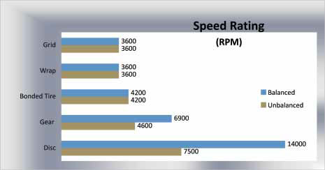
Figure 2
An added advantage for disc couplings is low potential unbalance, which makes their balance more repeatable. In other words, the balance achieved on the balance machine with a disc coupling will have the best chance of being repeated in the field.
Torsional Stiffness
Each type of coupling has unique stiffness characteristics that can be used to meet application requirements (see Figure 3). In applications such as an indexing conveyor or a paper machine drive, where the drive output and input need to be closely in phase, a torsionally stiff coupling like a disc or gear coupling may be the better choice. Disc couplings, although not as stiff as gear couplings, offer the benefit of no backlash. To reduce the severity of shock loads, elastomeric couplings can be used to provide softer starts than a gear or a disc coupling. Many of these designs can exhibit torsional windup of up to 6 deg at rated torque.
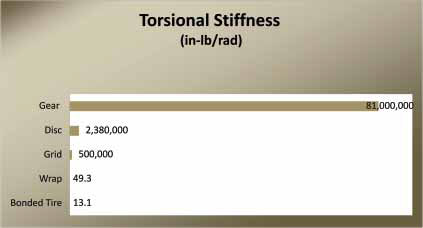
Figure 3
Torsionally soft couplings may also be employed to avoid vibration from operating at system natural frequency, either by shifting the system natural frequency or by dissipating the vibrational energy associated with system resonance. Grid couplings are a good compromise of soft and stiff, offering the strength of steel and the softness of an elastomer. This coupling design can reduce transmitted vibration by about 30 percent compared to a gear or disc coupling.
Weight
In our comparison, where a spacer coupling is required, a bonded tire or disc design may be the best choice for the lightest weight options (see Figure 4). For higher horsepower or close-coupled applications, particularly for extremely high horsepower applications, gear couplings will be the lightest weight option by far, resulting from their high torque density.
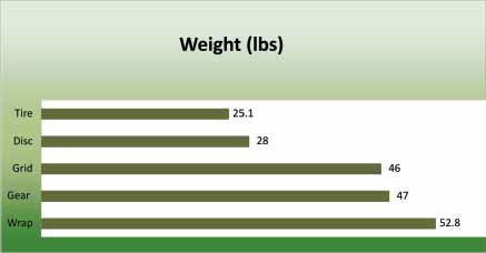
Figure 4. Weight
Torque Density
Torque density (see Figure 5) is expressed most accurately as torque capacity per unit volume. We will express torque density modified as meaning coupling torque rating/coupling weight.
For a flexible coupling, nothing compares to a gear coupling for transmitting the most torque in the lightest and smallest package.
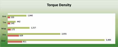
Figure 5. Torque Density
Temperature
Disc couplings offer the highest temperature rating due to their entirely metallic construction. The other coupling types are limited by either their elastomeric components such as flex elements or seals or by the temperature limitations of their lubricants (see Figure 6).
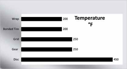
Figure 6. Temperature
Thrust Forces
As a result of speed, torque or their combination, couplings may impart axial forces or deflections into connected equipment. See Figure 7 for a comparison of relative thrust forces for typical coupling types.
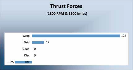
Figure 7. Thrust forces
When a coupling connects two axially restrained shafts, the coupling may impart forces into the bearings. These forces should be reviewed to ensure that the thrust capacity of the bearings is not exceeded. If the coupled shafts are not fully restrained, the coupling may move one or both shafts axially in an attempt to equalize forces. Applications involving axially sensitive equipment such as sleeve bearing motors or herringbone gear sets should be reviewed to ensure that the coupling travel will not cause equipment damage. Many couplings can be supplied with accessories such as gap discs, rung spacers or limited end float rings to limit this axial travel.
In their standard configuration, only a disc or gear coupling will not impart axial forces into the equipment. Of the two, only a disc coupling will truly limit end float, since it acts like a spring in both directions to hold the shafts axially in the position they were installed. This property makes them the ideal choice for sleeve bearing applications.
Conclusion
In addition to the application conditions described above, consider other secondary selection factors including duty cycles, environmental conditions, degree of maintenance, overall cost and expected service life. Familiarity and availability of a given coupling design may also impact the final decision.
Manufacturer's guidelines should be followed for periodic inspections, lubrication and other areas of attention that a coupling may require. Disc couplings, for example, do not require lubrication but should be inspected during scheduled shutdowns for any fretting, cracking or spreading/separating discs, which can indicate excessive misalignment or torque.
A coupling manufacturer with a broad product line and staff of experienced application engineers will be able to provide advice that leads to an optimum coupling choice.
Pumps & Systems, May 2010