


Internal clearance is one of the most important factors affecting bearing performance within pump applications. The bearing’s internal clearance is the relative movement of the outer and inner rings when they are lightly pushing in opposite directions. Movement in the diametrical direction is defined as radial clearance. Movement in the shaft’s direction is axial clearance.
Internal clearance is critical to bearing performance for multiple reasons. The amount of clearance influences the load distribution in a bearing, which ultimately affects bearing life. It also influences bearing running noise and vibration. In addition, it can influence whether the rolling elements move in a rolling or sliding motion.
Normally, bearings are installed with interference on either the inner or outer ring. This leads to its expansion or contraction, which causes a change in clearance. During operation, the bearing temperature will increase until it reaches saturation temperature. However, the temperature of the inner ring, outer ring and rolling elements are all different from each other, and this temperature difference changes the clearance (see Figure 1). In addition, when a bearing operates under load, an elastic deformation of the inner ring, outer ring and rolling elements also leads to a change in clearance. Quantifying all these changes can make calculating bearing internal clearance a complex task.
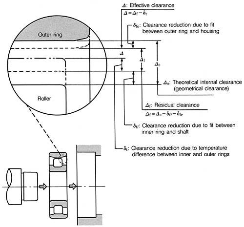 |
| Figure 1. Changes of radial internal clearance of a roller bearing |
Different Types of Clearances
What is the ideal clearance? Before considering this question, different types of clearance will be defined in this section.
Measured Internal Clearance (∆1)
This is the internal clearance measured under a specified measuring load and can be called apparent clearance. It includes the elastic deformation (δFO) caused by the measuring load.
∆1 = ∆0 + δFO
Theoretical Internal Clearance (∆0)
This is the radial internal clearance, which is the measured clearance minus the elastic deformation caused by the measuring load.
∆0 = ∆1 + δFO
δFO is significant for ball bearings but not for roller bearings, where it is assumed to be equal to zero, and therefore ∆0 = ∆1.
Residual Internal Clearance (∆f)
This is the clearance left in a bearing after mounting it on a shaft and in a housing. The elastic deformation caused by the mass of the shaft, etc., is neglected. Assuming the clearance decrease caused by the ring expansion or contraction is δf, then:
∆f = ∆0 + δf
Effective Internal Clearance (∆)
This is the bearing clearance that exists in a machine at its operating temperature, excluding the elastic deformation caused by load. In other words, this is the clearance when considering only the changes because of the bearing fitting δf and temperature difference between the inner and outer rings, δt. The basic load ratings of bearings apply only when the effective clearance is ∆=0.
∆ = ∆f − δt = ∆0 – (δf + δt)
Operating Clearance (∆F)
This is the actual clearance when a bearing is installed and running under load. In this situation, the effect of elastic deformation δF is included and the fitting and temperature. Generally, the operating clearance is not used in the calculation.
∆F = ∆ + δF
Importance of Effective Clearance
The most important bearing clearance is the effective clearance. Theoretically, a bearing with a slightly negative effective clearance ∆ will have the longest life. A slightly negative clearance (or preload) will actually become positive under the influence of bearing load. However, making the clearance of all the bearings the ideal effective clearance is impossible. End users must consider the geometrical clearance ∆0 to achieve a zero or slightly negative effective clearance minimum value. To calculate this value, a user needs to know the clearance reduction caused by the interference of the inner ring and outer ring δf and the clearance change caused by the temperature difference between the inner ring and outer ring, δt.
Calculating Residual Internal Clearance After Mounting
When the inner ring of a bearing is press fit onto a shaft, or when the outer ring is press fit into a housing, the radial, internal clearance will naturally decrease because of the resulting expansion or contraction of the bearing raceways. Generally, most pumps have a rotating shaft that requires a tight fit between the inner ring and shaft and a loose fit between the outer ring and housing. In these cases, only the effect of the interference on the inner ring needs to be considered.
An example calculation is shown below for a 6310, single-row, deep-groove ball bearing. The shaft tolerance used is K5, while the housing is H7. The interference fit is applied only to the inner ring.
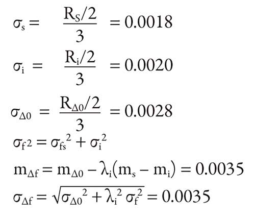
Shaft diameter, bore size and radial clearance are the standard bearing measurements. Assuming that 99.7 percent of the parts are within tolerance, the mean value (m∆f) and standard deviation (σ∆f) of the internal clearance after mounting (residual clearance) can be calculated. Measurements are given in millimeters (mm).
Where:
σs = Standard deviation of shaft diameter
σI = Standard deviation of bore diameter
σf = Standard deviation of interference
σ∆0 = Standard deviation of radial clearance (before mounting)
σ∆f = Standard deviation of residual clearance (after mounting)
ms = Mean value of shaft diameter (Ø50+0.008)
mi = Mean value of bore diameter (Ø50-0.006)
m∆0 = Mean value of radial clearance (before mounting) (0.014)
m∆f = Mean value of residual clearance (after mounting)
Rs = Shaft tolerance (0.011)
Ri = Bearing bore tolerance (0.012)
R∆0 = Range in radial clearance (before mounting) (0.017)
λI = Rate of raceway expansion from apparent interference (0.75 from Figure 2)
The average amount of raceway expansion and contraction from apparent interference is calculated using:
λi (mm – mi).
The following equation is used to determine, within 99.7 percent probability, the variation in internal clearance after mounting (R∆f):
R∆f = m∆f ± 3σ∆f = +0.014 to -0.007
In other words, the mean value of residual clearance—(m∆f) is +0.0035—and the range are from -0.007 to 0.014 for a 6310 bearing.
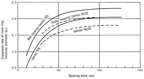 |
Figure 2. Rate of inner ring raceway expansion (λi) from apparent interference
Radial Internal Clearance and Temperature
When a bearing runs under a load, the temperature of the entire bearing will rise. This includes the rolling elements. However, because this change is extremely difficult to measure or estimate, the temperature of the rolling elements is generally assumed to be the same as the inner-ring temperature.
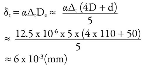
Using a 6310 bearing again as an example, the reduction in clearance caused by a temperature difference of 5 C between the inner and outer rings can be calculated using the following equation:
Where:
δτ = Decrease in radial internal clearance caused by a temperature difference between the inner and outer rings (mm)
α = Linear thermal expansion coefficient for bearing steel, 12.5 x 10⁻⁶ (1/ C)
∆t = Difference in temperature between inner ring (or rolling elements) and outer ring (C)
D = Outside diameter (6310 bearing, 110 mm)
d = Bore diameter (6310 bearing, 50 mm)
De = Outer-ring raceway diameter (mm)
The following equations are used to calculate the outer-ring raceway diameter:
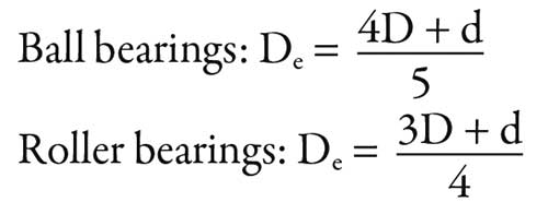
Using the values calculated for ∆f and δt, the effective internal clearance (∆) can be determined using the following equation:
D = Df – dt = (+0.014 to -0.007) – 0.006
= +0.008 to -0.013
In Figure 3, note how the effective internal clearance influences bearing life, in this example, with a radial load of 3,350 Newtons (or approximately 5 percent of the basic load rating). The longest bearing life occurs under conditions in which the effective internal clearance is -13 micrometers. The lowest limit to the preferred effective internal clearance range is also -13 micrometers.
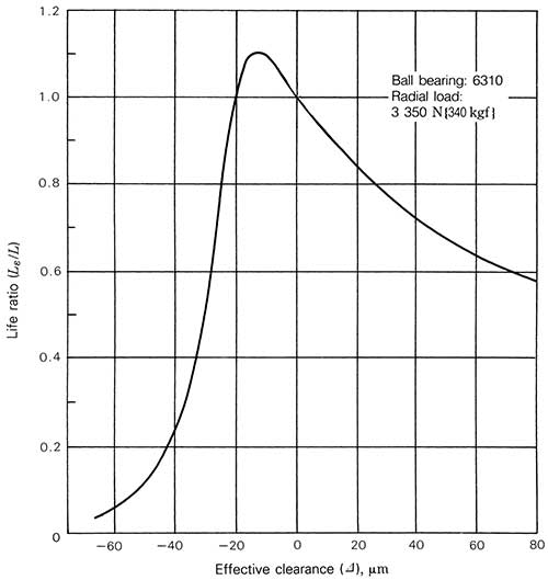 |
| Figure 3. Relationship between the effective clearance and the bearing life for a 6310 ball bearing |
Application
In theory, targeting a slightly negative clearance is optimal for bearing life. However, in practice, end users must be careful when designing or building a pump with bearing preload. As shown in Figure 3, the life ratio peaks at -13 micrometers, but decreases dramatically with additional preload. Incorrect assumptions regarding machining tolerances or operating temperatures can easily result in a shorter life than anticipated if the bearing becomes preloaded too heavily.
On the other hand, too much clearance can result in the bearing slipping and poor pump performance. End users must evaluate the trade-offs of clearance and bearing preload based on the needs of the application. Understanding the importance of bearing internal clearance will help increase bearing life and optimize overall pump performance. P&S