


Pumps & Systems, July 2007
Last month we took a close look at the flow of voltage and current in purely resistive and inductive circuits. We showed how inductive reactance can inhibit the flow of primary current in a circuit and how this lagging effect determines the value of power factor (PF).
Although the purely resistive and inductive examples we used helped us understand what was happening, they do not represent a typical electrical circuit. Almost all circuits are a combination of resistive and inductive loads and, in some cases, those that are capacitive as well. Motors, arc welders, transformers, heaters, incandescent lighting, ballast lighting, solid state power supplies, and many other electrical devices contribute to the overall load on the circuit.
Figure 1 shows a more typical circuit that is feeding both resistive and inductive devices. The impedance (Z) of the circuit (in Ohms) is √R2 + XL2, where R is the resistance and XL is inductive reactance.
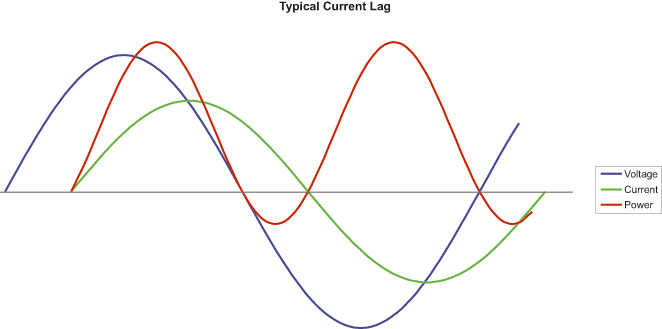 Figure 1
This example assumes that these values are relatively equal and results in current lagging voltage by about 45-deg. The power factor of this circuit is about 0.7 (cosine 45 = .707), which means that about 70 percent of the actual power in the circuit is available to do real work. The remainder or "reactive" power is returned to the circuit as the inductive fields decay.
Now, you will have to admit that this circuit looks a whole lot better than the purely reactive one we saw last month. But almost 30 percent of the power in the circuit is still unusable, and that can result in some undesirable consequences.
Consequences
So what are the consequences of low PF? Basically, there are two.
The first one involves power generation. We have all seen what happens when there is a voltage drop in a circuit feeding an electric motor. The voltage drop creates a net reduction in watts needed by the motor, but the motor couldn't care less. It simply increases its current demand in amps and gets watts back to their original level.
A similar thing occurs when inductive reactance causes current to lag voltage. The circuit uses additional current to make up for those areas of the curve where power is unavailable. And where does that additional current come from? The utility, of course, and if that additional current is not already in the system, they have to generate it. Now the last thing a utility wants to do is add generating capacity, so they will typically charge consumers a surcharge if their total PF is below some required minimum.
The second consequence has to do with power distribution and it can affect both the utility and the consumer. In an electrical circuit, the energy expended (as heat) in maintaining current flow increases as the square of current intensity. Double the current and losses increase fourfold. This is the reason why long distance power transmission lines employ very high voltages (and lower currents) and then reduce that voltage at the point of use.
As PF declines, current increases and so do losses due to heat. At some point, the wire size must be increased in order to prevent further losses. For example, suppose an electrical system can use 0 AWG cable to supply 100-KW at 460-V at a PF of 100 percent. If PF is reduced to 70 percent, the cable size will increase to 000 AWG! And it's not just wire size. Every other component in the system (supply transformer, switch gear, etc) must also be oversized if it is to accommodate the additional current required by a low PF installation.
At a PF of 100 percent, that same electrical system could utilize a transformer rated at 100-kVA. Reduce PF to 70 percent and 143-kVA would be required.
Motor Power Factor
No AC induction motor can have a PF rating of 100 percent. Why? Because a portion of the total power it requires is used to create that magnetic field in the stator and, as we have seen, that portion is not actually consumed, but is returned to the circuit.
As a rule of thumb, higher speed motors (those with fewer poles) will have a higher PF than lower speed motors. And larger motors will have a higher PF than smaller ones. If you look at a cross section of low voltage (230/460) NEMA frame motors available today, PF ranges from a low of about 53 percent at 1-hp to a high of about 96 percent at 250-hp.
It is virtually impossible to design a motor that optimizes all of its major operating characteristics. And if you made PF the priority, other important variables such as efficiency, torque, and temperature rise would suffer. For example, a reduced air gap between the rotor and stator increases PF, but has the exact opposite effect on efficiency.
Fortunately, there is an aftermarket method of improving a motor's PF that allows the designer to concentrate on those other (more important) characteristics that cannot be changed in the field.
Fixes
There are several ways to improve PF. The most common one will increase the PF of a motor, other inductive devices or the entire system as a whole. Another involves the use of synchronous motors. Still another, the VFD, is limited strictly to single motors. Let's look at the first one and save the others for another column.
So far we have seen examples of circuits that are purely resistive, purely inductive, and one that is a combination of the two. There is, however, another type - the purely capacitive load.
The capacitor is a very simple, yet interesting and useful electronic device. It is similar to a battery in that it stores a charge but, unlike the battery, it does not produce electrons through a chemical reaction. It simply stores them for use at some later time.
Another difference between a capacitor and a battery is the discharge rate. A battery discharges slowly, over a period of hours or days, while the capacitor can release its entire charge in a few milliseconds! Its design consists of two metal plates that are kept from touching one another by some dielectric material (insulator).
When a capacitor is placed in a DC circuit, the plate that is connected to the negative terminal accepts electrons while the other plate loses electrons. When it is fully charged, voltage reaches its maximum and the flow of current in the circuit ceases.
When a capacitor is placed in an AC circuit, current behaves differently. It flows continuously because the capacitor is always charging and discharging due the changing polarity of the AC wave form. These rapid changes have an effect on the voltage and current waves similar to the one we saw in an inductive circuit. But it is exactly backwards - voltage lags current.
Unfortunately, this particular lagging relationship or "capacitive reactance" is more complex than its inductive cousin. Let's just say that it has to do with frequency and the time required for voltage and current to change within the capacitor. But the result is the important point.
Figure 2 shows the relationship of voltage and current in a purely capacitive circuit. Here we see the exact opposite of the inductive circuit we saw last month - voltage is lagging current by 90-deg. As with inductive reactance, power is not consumed during charging, but is returned to the circuit when the capacitor discharges.
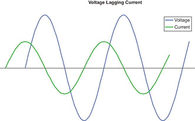 Figure 2
The addition of capacitive reactance to a circuit containing both resistance and inductive reactance changes our equation for impedance in a very beneficial way. Now we have √R2 + (XL2 - XC2), where XC is capacitive reactance. If capacitive reactance and inductive reactance are equal, reactance goes away and the circuit becomes purely resistive!
When properly sized capacitors are added to a circuit that contains an inductive load, power factor will increase. This occurs because the current leading effect of the capacitor will cancel all or a part of the current lagging effect of the inductor.
There are a couple of different ways of using capacitors to improve power factor.
The most simple, "static" correction, will increase the PF of an individual motor. In this application, an appropriately sized capacitor is installed in parallel with the motor windings and is located between the starter (across the line) and the motor. In this location, the capacitor will always be in the circuit when the motor is running and then removed automatically when the starter disengages. Its removal prevents possible overcorrection when the motor is not running.
It is important to follow the motor manufacturer's guidelines when sizing a static capacitor in order to avoid under- or over-correction. As a rule of thumb, correction usually should not exceed 80 percent of the motor's magnetizing current. Static correction capacitors should not be installed on the output side of a solid-state soft starter because of the potential damage that they can cause. In these installations, capacitors should be located on the input side and well upstream of the soft starter.
Another method is known as "bulk" correction. In this form of PF improvement, a group or bank of capacitors can be installed right after the supply transformer to correct the PF of the entire system that it feeds. A controller monitors the total power factor of the system and switches groups of capacitors on and off depending upon the inductive load at any point in time.
Bulk correction can approach unity (PF = 1), but a PF of 90 percent to 95 percent is more typical. Adding capacitance to correct power factor can be a relatively easy and inexpensive fix for a potentially expensive problem.
There is, however, a growing PF problem that cannot be fixed by adding capacitors to a circuit: switched mode power supplies which are found in personal computers and other electronic devices use rectifiers and switching transistors to regulate voltage.
These nonlinear components produce harmonics that can feed back into the circuit and, if there are a significant number of these devices, overall PF can be reduced. This is becoming a significant concern for utilities because capacitors alone will not fix the problem. Expensive filters, composed of high current inductors, are needed to remove the harmonics and return the current to its linear form. Because of this, we are beginning to see mandated PF correction for power supplies that exceed a certain power requirement.