


Q. What information is available regarding boiler circulating pumps for combined-cycle power plant service?
A. Boiler circulating pumps circulate water within the boiler to enhance boiler operation. They take suction from a header that is connected to several downcomers from the bottom of the boiler drum and discharge through additional tube circuits. This means the water pumped is at boiler temperature and pressure. Boiler circulating pumps are designed for high temperatures (usually between 150 C and 315 C [300 F and 600 F], depending on boiler size and rating) and high pressure (corresponding to boiler temperature and water vapor pressure). For small boilers with relatively low temperatures and pressures, conventional overhung pump designs—such as Hydraulic Institute (HI) pump type OH2 (see Image 3.11)—may be suitable for boiler circulating service. Boiler circulating pumps must develop only enough head to overcome the friction of the tube circuits. However, the combination of high temperature and pressure results in conditions that require special sealing devices.
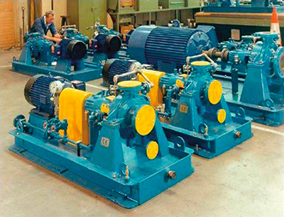 Overhung impeller pump (OH2). Image courtesy of Sulzer Pumps
Because of the relatively low head requirements, the pumps are single stage with single-suction impellers and a single seal chamber. This creates an unbalanced axial thrust problem, which may require special pump bearing systems or balancing arrangements. An alternate solution is to use wet motor construction pumps, in which the pump and the motor are inside the pressure vessel, eliminating sealing and unbalanced axial thrust issues. These special pumps are welded into the boiler piping. For higher temperatures up to 365 C (685 F) and pressures from 124 to 193 bar (1,800 to 2,800 psi), special pump designs are required. For more information about boiler circulating pumps and their application in combined-cycle power plants, see Power Plant Pumps: Guidelines for Application and Operation to Maximize Uptime, Availability, and Reliability.
Q. How are auxiliary cooling water pumps (acw pumps) used in combined-cycle power plant service, and what pump types can be used?
A. Auxiliary cooling water pumps (see Figure 6.15) usually operate in a closed-loop system using high-quality water. The water received from the circulating water pumps moves through the tube side of the auxiliary cooling water heat exchanger. The auxiliary cooling water circulates through the shell side and is cooled. The auxiliary cooling water then proceeds to small heat exchangers used for cooling the pump and motor bearing frames, mechanical seals and other equipment. The fluid pumped from auxiliary cooling water pumps is clean, high-quality water, unlike the main cooling system, which takes water directly from the cooling tower or other sources. Clean, high-quality water is used to cool pump, fan and motor bearing frames; mechanical seals; and heat exchangers because they could be easily plugged if the cooling water contains high levels of suspended or dissolved solids. The fluid temperature usually ranges from 10 C to 27 C (50 F to 80 F).
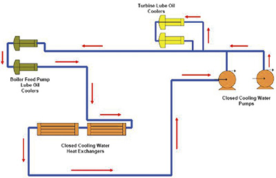 Closed-loop cooling water pump flow diagram
Auxiliary cooling water pumps may be either single or multistage, depending on the pressure and flow requirements of the system. Single-stage, end-suction pumps of the heavy-duty process types (OH1, OH2 and BB1) are popular for both low- and medium-pressure service. For higher pressures, multistage pumps (VS6 types) are used. The castings (metallurgy) for subject pumps can be all cast iron or ductile iron. However, for VS6 pump types, the castings should be carbon steel. A typical upgrade for these pumps would be carbon-steel castings with 12 percent chrome stainless impeller and wear rings. For more information about the pump types used in combined-cycle power plants, see Power Plant Pumps: Guidelines for Application and Operation to Maximize Uptime, Availability, and Reliability.
Q. How should a mounting base be designed and installed for a sealless rotodynamic pump?
A. For close-coupled configurations (magnetic drive housing mounted to motor flange), a rigid mounting base is not required, because piping strains do not affect shaft alignment. Allowable flange loading shall be specified by the manufacturer but is not related to coupling deflection. For magnetic drive designs using flexible shaft couplings, the baseplate design shall be suitable for grouting to a rigid foundation if it is necessary to handle rated flange loading with acceptable misalignment at the flexible coupling. Allowable flange loading to avoid malfunction of internal components shall be specified by the manufacturer. Mounting pads or contact surfaces of the baseplate shall be provided for the pump and drive train components, shall be flat and parallel, and should be larger than the feet of the mounted equipment. Pads or contact surfaces for drive train components shall allow for the installation of shims at least 3 millimeters (0.125 inch) thick under the driver. A set of stainless-steel shims at least 3 millimeters (0.125 inch) thick shall be furnished. The pump and its baseplate shall be constructed with sufficient structural stiffness, when properly grouted, to limit the displacement of the drive end of the pump shaft to 0.25 millimeter (0.01 inch) using the most severe combination of forces and moments for which the manufacturer rates the product. When epoxy grout is specified on the data sheet, the manufacturer shall pre-coat all surfaces of the baseplate that will be in contact with the grout with a catalyzed epoxy primer. The primer shall be applied according to the paint manufacturer’s recommendations. Anchor bolts shall be furnished by the purchaser. A magnetic drive may be used for a vertical submerged pump. Particular attention shall be given to venting the containment shell. For more information about sealless rotodynamic pumps, see ANSI/HI 5.1-5.6 Sealless Rotodynamic Pumps for Nomenclature, Definitions, Application, Operation, and Test.