


Figure 1 plots the clearances specified for wear rings in API 610 (1) and in the Pump Handbook (2) as a function of the ring diameter. To obtain optimum (hydraulic and mechanical) performance, manufacturers want to provide centrifugal pumps with minimum clearance between wear rings.
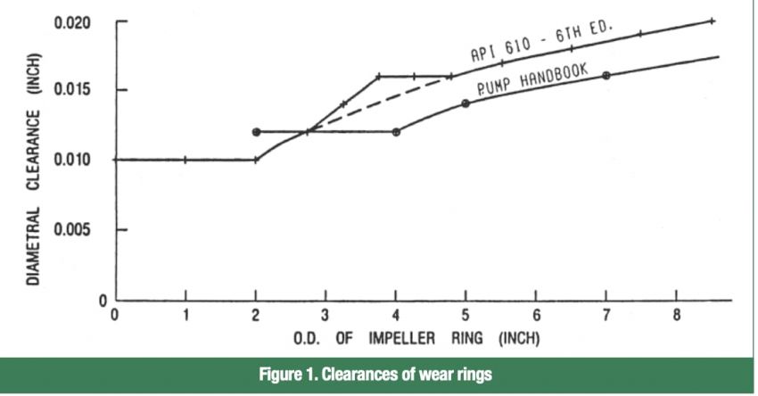
To reduce the chance of galling and seizing between mating rings, users want the clearance to be large. Users often do not fully realize the negative impact of increased ring clearance on the hydraulic and mechanical performance of a centrifugal pump. A plant repair shop will sometimes increase ring clearances the first time a pump is serviced. This usually does reduce the chances for ring seizure, but it has numerous undesirable side effects.
Hydraulic Effects of Wear Ring Clearances
Tests have shown that wear ring clearances significantly impact the performance of centrifugal pumps, particularly those with lower specific speeds.
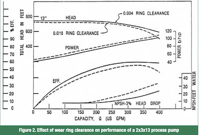
The effect of wear ring clearance on the performance of a pump is shown in Figure 2. This is a 2x3x13 hydrocarbon process pump, which is built in both horizontal and in line configurations. The single suction impeller is equipped with rings at the eye and on the back side (conventional con- struction). The diameter of the throttling surface of both sets of rings is 4 3/8 in. The lower head curve shows the performance of this pump with a 0.018 in diametral ring clearance is only 0.002 in more than the minimum specified by API 610 (1) for a 4 3/8 in throttling surface. The upper curve shows pump head with the ring clearance reduced to 0.004 in. (To operate with such a small clearance, special casing rings were designed that are free to float and align themselves with the impeller rings.)
With the tighter rings, the head increased about 20 ft (3 percent). The reduction in power was more significant— about 6 bhp (7 percent). Efficiency increased about 5 points (10 percent). The reduction in NPSHR ranged from 0 to about 10 ft.
Because we plot the characteristics of a centrifugal pump against capacity, we tend, as we did above, to consider the change in characteristics at each individual capacity. We say that the head increased, the power dropped and the NPSHR dropped. These are all correct statements, but it is easier to understand these changes if we consider the head, power and NPSHR to be constants, and the pump capac- ity to be increased by the amount that the internal leak- age was decreased. With this approach, we can see that the power curve shifted uniformly about 32 gpm to the right, a number that agrees well with the calculated reduction in ring leakage. The head curve also shifted about 32 gpm to the right.
The NPSH curve shifted to the right, anywhere from 50 to 75 gpm; the excess over 32 gpm being the compound effect of the capacity change, the reduced energy level of the liquid leaking back into the impeller eye and the reduction in the disturbance of the eye flow pattern.
This pump has a specific speed of only about 500, so the proportion of the total flow attributable to ring leakage is greater than for larger pumps with 13 in. impellers. The proportional impact on pumps with higher specific speeds would be less than seen above, although the absolute change in power would be larger.
Understanding NPSH Effect of Other Throttling Devices
Other throttling devices have the same effect on pump efficiency and NPSHR.
Balancing Device
A horizontal, multistage pump is typically equipped with a balancing device (drum, piston or sleeve) that provides axial hydraulic balance for the pump (to lessen the load on the thrust bearing). For this device to function, it must throttle pumpage from some internal high pressure (half or full pump head, depending on pump style) all the way down to suction pressure. This liquid is then normally piped back to the inlet of the first stage impeller.
Because this “balancing” leakage has been through the pump, then past the balancing drum, it enters the eye of the first stage impeller warmer than the first time it entered the pump. The higher temperature causes the vapor pressure to be higher, thereby requiring a higher inlet pressure to suppress cavitation. That is higher NPSHR.
The higher the leakage through the balancing device, the lower the pump efficiency and the higher the NPSHR. The clearance between the balancing device (the rotating part) and its bushing (the stationary part) must be maintained at the manufacturer’s recommended value to retain rated NPSHR.
The pump NPSH requirement can be reduced by piping the leakage from the balancing device back to the suction vessel, instead of to the pump suction, but all valves in this line must be locked open. (The closure of any valve in this line, while the pump is running, can over pressure the seal and wreck the thrust bearing.)
Throat Bushing
In a vertical, multistage, “turbine” pump, a long throat bush- ing throttles discharge pressure, down to suction pressure, to reduce the pressure on the packing or mechanical seal. This leakage is normally piped back to the top of the can (into the suction cavity).
This pumpage is heated by passing through all impellers and bowls, then heated again as it is throttled to suction pres- sure. As with the balancing leakage discussed above, when this warmer liquid flows into the eye of the first stage impeller, the pump NPSHR rises.
As the clearance in this bushing increases, the flow though it increases, which causes not only a reduction in pump effi- ciency, but also an increase in NPSHR. The clearance between the throat bushing and the shaft must be maintained at the manufacturer’s recommended value to retain rated NPSHR.
the leakage from the throat bushing back to the suction vessel, instead of to the pump suction, but all valves in this line should be locked open, to prevent over pressuring the seal.
Seal Flush
A mechanical seal is usually “flushed” by taking pumpage from the discharge of the pump and throttling it though an orifice. It then passes across the seal, from which it flows through the throat of the seal chamber, into the back ring of the impeller through the impeller “balance holes,” and into the impeller eye.
This pumpage gets heated by passing through the pump, then through the orifice, then past the seal. All this heat increases the vapor pressure of the liquid. More pressure is therefore required at the pump inlet to prevent cavitation of this flush liquid (i.e., more NPSH is required).
The impact of seal flush on NPSHR can be minimized by minimizing the flow rate. Provide no more flush than is required to satisfy the seal naturally with a suitable margin. Excessive flushing can actually damage the seal.
The author is aware of a propane pump whose NPSHR was reduced by venting the seal chamber to the suction vessel.
References
1. Centrifugal Pumps for General Refinery Service, API Standard 610, American Petroleum Institute, 1220 L Street NW, Washington, DC 20005
2. Karassik, I.J., et al, Pump Handbook, McGraw Hill Book Co., New York, NY, 1976.