


In this case study, routine maintenance of a condensate pump at a nuclear power plant becomes an emergency situation.
When a nuclear power plant pulled its vertical condensate pump for routine maintenance, an emergency situation was not expected. The plant pulled the pump and installed a replacement from storage, but it failed catastrophically after only two days in service.
Requiring a solution for the emergency need, the plant accepted a workscope from a service center that promised a refurbished pump within nine days. The plant shipped both pumps to the service center and sent a condensate system engineer to oversee the work and maintain an open line of communication between the organizations.
This case study highlights the root cause of pump failure for a nuclear power plant and the emergency response required to repair the pump.
Teamwork Critical to Quick Turnaround
One key factor to successfully handling this emergency pump failure was the close teamwork between the plant's management, an onsite plant engineer located at the repair facility and the personnel at the repair facility. A lesson learned for pump users in emergency situations is that close teamwork and having a customer engineer onsite is critical to facilitating a rapid response.
Root Cause of Failure
The pump failed as a result of having been previously incorrectly repaired, coupled with contributing installation issues, ultimately causing the upper shaft to break. Evidence of the root cause became apparent during the disassembly process. These photos illustrate what the pump service center found.
Ductile Fatigue Failure: The head shaft cracked at the snap ring groove just before the last stage impeller front hub ring turn.
Best practice is to maintain stringent alignment and concentricity between interfacing parts. This ensures correct concentricity and perpendicularity between shaft and bearings and rotor to casing. The service center discovered that the top bowl male fit had been previously repaired by pad welding (see Figure 1), which is an improper practice due to the presence of a sealing O-ring. When a pad weld is performed on a pump that uses the O-ring design, fits and tolerances no longer meet acceptance criteria. It appears that the previous repair provider coated the faces with silicone or another sealant in an attempt to re-establish the proper fits or control leakage (see Figure 2).
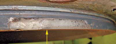
Figure 1. Pad welded male fit for the top bowl.
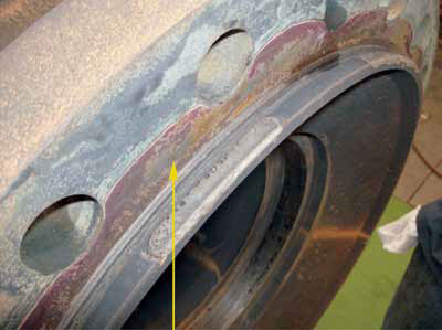
Figure 2. Silicone coating appears to have been used in a previous repair after the male fits were pad welded in an attempt to seal the proper fit between the top bowl and the discharge head.
The top of the discharge bowl did not fit properly in the bottom of the discharge head (see Figure 3). Excessive force used to make these components fit bent the shaft and created a condition ripe for fatigue failure. The forced bending of the shaft caused the impeller ring to contact the case (bowl) ring during operation (see Figures 5 and 6). The motor had to produce more torque to drive the assembly due to frictional resistance from the heavy rub (see Figure 7). Furthermore, the suction bell was not properly seated in the alignment ring (see Figure 8).
The misalignment and excessive bending load on the entire rotating element assembly caused the shaft to break at the snap ring groove, which resulted in catastrophic pump failure.
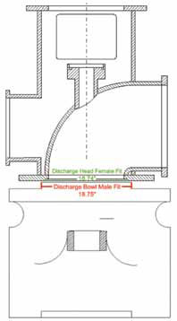
Figure 3. The male fit of the top discharge bowl was over size at 18.754 in. and the female fit of the discharge head was 18.7445 in., causing an interference fit (Exaggerated diagram, not to scale).
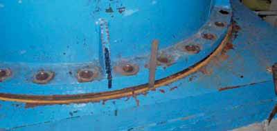
Figure 4. The bolts between the can flange and the discharge head appear to have been tightened with additional force as one section of the flange rose up about ¾ in. on one side after the discharge flange was unbolted from the base-plate.
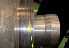
Figure 5. Damaged case ring as a result of galling contact.
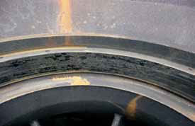
Figure 6. Heavy grooving from running stage impeller eye ring.
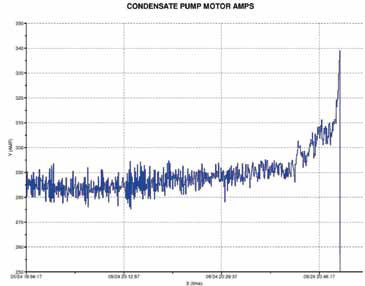
Figure 7. The high amps reading at pump failure show motor torque.

Figure 8. The alignment ring at the bottom has a damaged edge, which is evidence that the suction bell was not properly seated in the alignment ring.
Emergency Response Required to Repair the IR 32 APKD Nine-Stage Condensate Pump
The agreed plan to repair the pump was to use in-spec parts from the first pump and reusable parts from the failed pump to deliver one working pump. The plant's ability to supply condensate pump parts from its inventory helped decrease the turnaround time because fewer parts needed to be manufactured.
Bowls and Bearings
Bowls from the first pump were used because the impeller case wear ring running clearances were acceptable; however, the shaft graphalloy bearing running clearances were not. Fortunately, the plant had new bowl/shaft bearings in their inventory and provided them for use. After installing the bearings, bowl TIRs (wear ring and bearing bores) were checked. In the lower five bowls, the wear rings had excessive run-out. The plant had five bowl wear rings in stock that could be used with the impellers and bowls.
Shaft
The upper shaft from the original pump and the lower shaft from the failed pump were used because both had acceptable TIR readings of less than 0.003.”
Impellers
The impellers from the original pump had to be used because the bowls were taken from that pump and the impeller wear ring diameters were sized to those bowl rings. Each impeller was balanced individually to 1 W/N, and then each rotor was balanced (upper with five impellers and lower with four impellers).
Discharge Head
Plants often use a common discharge head in a given condensate pump position. Spare heads are not usually kept. Using the same discharge head with different bowl assemblies can affect the geometric centerline between the rotor and the casing as well as the head-to-bowl assembly. After inspection, the discharge head was welded and machined at critical fit locations to re-establish proper concentricity. The completed pump was shipped back to the plant within the agreed nine-day turnaround time.
Lessons Learned
There is no doubt that the disassembly, inspection, analysis and complete repair would have required much more time in a typical pump repair shop. The service center, which was dedicated to nuclear pump aftermarket services, was able to determine the root cause of failure and provide a rebuilt pump within nine days because they had an in-house engineering team and customer partnership during the repair process. Working with a pump service facility that combines experienced individuals using proper repair and rebuilding practices for vertical pumps is important. Vertical pumps require precision manufacturing and attention to detail during the rebuild and installation process because of their multiple components, which when assembled, result in a tolerance stack-up that must be concentric within fairly narrow limits from top to bottom.