


With today's energy prices, a plant's steam/condensate systems cannot afford to vent flash steam to the atmosphere. The non-modulating steam system's operational design allows the condensate and flash steam to be recovered in a flash tank system. This flash steam recovery system differs from a modulating steam system.
Flash Steam Recovery Systems (Non-Modulating Steam Conditions)
Condensate/flash steam (two-phase flow) discharging from a non-modulating steam system process can be recovered in a flash steam system or high-pressure condensate return system. Non-modulating steam condition means no control valve modulates steam flow to the process. If a control valve is present, the steam control valve always maintains a steam pressure to the process above the pressure in the condensate recovery system.
A non-modulating process steam system provides a constant steam pressure to the process, thus providing a constant pressure differential across the steam traps or condensate discharge control valve. See Figure 1.
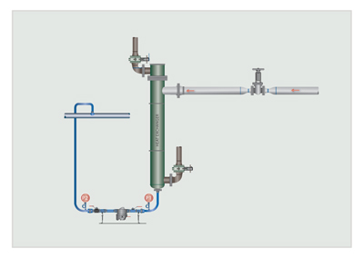
Figure 1. Non-modulating steam system
The two-phase flow (flash/condensate) from the process discharge can be directed to the pressurized flash tank for separation. The purpose of the flash/condensate separation process is to separate the flash steam and condensate, leaving no entrainment of condensate into the flash steam. The flash steam can then be delivered to a lower pressure steam line. This method is referred to as a cascading flash steam system. In a high pressure condensate return system, the high pressure in the condensate return line greatly reduces the percentage of flash steam, and typically the flash steam is used for the deaerator steam consumption.
Examples of Non-Modulating Steam Processes
- Steam tracing
- Drip leg steam traps
- Unit heaters
- Process heater
- Reboilers
- Corrugators
- Flash Recovery System
The above steam systems do not have a modulating steam control valve for the process, or if there is a control valve, the steam control valve always maintains a steam pressure to the process above the pressure in the condensate recovery system. There is always a higher steam pressure to the process than the condensate return line, which will provide a constant pressure differential across the steam traps or condensate control valve. See Figure 2.
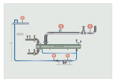
Figure 2. Flash recovery system
With proper sizing and installation of a flash tank, the flash steam may be used for the heat exchanger device to heat air, water or any other liquid, or it may be used directly in processes with lower pressure steam requirements. Flash steam can be generated directly by discharging high pressure condensate to a lower pressure steam system. This practice is seldom used in industrial applications. The best practice is to use a flash tank to provide the following:
- Separation of condensate and flash steam
- Control the flashing process
- Allow enough space for flash steam to be released
- Reduce the velocities of the flash steam to ensure no condensate carryover with the flash steam
Flash tanks can be mounted either vertically or horizontally. The vertical arrangement shown in Figure 3 is the preferred method because it provides better separation of steam and condensate, resulting in the highest possible flash steam quality.
The most important dimension in the design of vertical flash tanks is the internal diameter, which must be large enough to ensure a low discharge velocity of flash steam to minimize condensate carryover. The tank sizing requires sufficient surface area for the release of the flash steam from the condensate. If the condensate return line is properly sized, the condensate will release the flash steam in the condensate line: therefore, the flash tank becomes a separator tank (flash and condensate). Outlet velocities from the flash tank should not exceed 3,000 feet per minute. Unfortunately, most condensate lines found in industrial operations are not properly sized, so the flash tank has to provide the proper area for the condensate to release the flash steam.
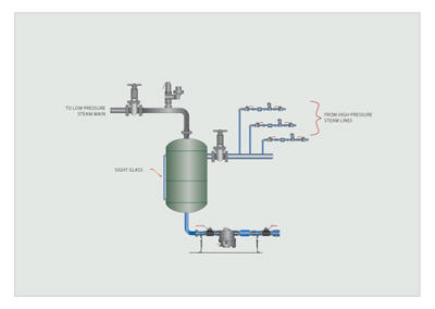
Figure 3. Vertical flash tank arrangement
In Figure 3, the flash steam is used in a cascade steam system: that is, the flash steam is delivered to the lower pressure steam system. The steam demand must always be greater than the amount of flash steam available to prevent the low pressure steam system from becoming over-pressurized. A safety relief valve should always be installed at the top of the flash tank or steam line piping to preclude an over-pressurized situation in the steam line. In a typical cascade flash steam system, the flash steam generated is generally less than the demand for low pressure steam system and a pressure reducing valve or makeup steam valve is added to the system to ensure the low pressure steam system maintains the correct operating pressure.
A large number of plants do not need low pressure steam, so the cascade steam system is not a benefit. Another method to recover the flash steam is to use a thermocompressing system. Thermocompressing takes the low pressure steam and produces a higher, usable steam pressure. The thermocompressor is a simple device that has existed for many years. It has a nozzle where high pressure steam is accelerated into a high velocity fluid. The high velocity entrains the low pressure steam from the flash tank by momentum transfer and then recompresses it in a divergent venture. The result is an intermediate steam pressure useful to the plant operation.
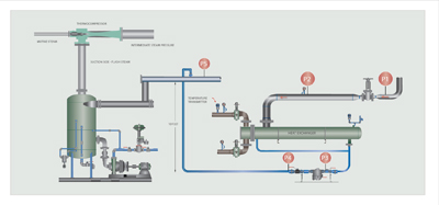
Figure 4. Thermocompressing system
Flash tanks are considered pressure vessels and must be constructed in accordance with ASME and local codes.
Checklist
1. Define all the non-modulating steam processes.
2. Determine whether cascade or thermocompressing is the best method
3. Recover the flash steam.
Steps to Designing a Flash Tank
1. Calculate the Amount of Condensate Entering the Flash Tank
The amount of condensate entering the tank will be the sum of the steam-consuming capacity of all equipment discharging into the condensate return line that is going to the flash tank. This could be one component or multiple components.
Example: 25,000 lbs per hour (11.3 ton/hr)
2. Determine the Process Pressure and Flash Tank Pressure.
Example: Process pressure: 150 psig (10.3 bar)
Flash tank pressure: 10 psig (.7 bar)
3. Calculate the Condensate that Flashes to Steam
Formula: % Flash = High Sensible Heat - Low Sensible Heat
Low Latent Heat
% Flash = 338.4 Btu @ 150 psig (10.3 bar) - 207.9 Btu @ 10 psig (.7 bar)
952.6 Btu @ 10 psig (.7 bar)
Example: 13.7 % = 338.4 - 207.9 Btu
952.6 Btu
25,000 lbs per hour (11.3 ton/hr) divided by 13.7 percent = 3,425 lbs/hr (1.7 ton/hr) Flash Steam
4. Size the Steam Space
If the condensate line is adequately sized, a high percentage of the steam flashing will occur in the condensate line. The steam section of the tank need only be sized to take care of the instantaneous flash. Unfortunately, a high percentage of the condensate lines in the industrial plants are undersized from a number of reasons.
Therefore, the following example should be followed in sizing the steam section of the flash tank:
3,425 lbs/hr x 16.5 (specific volume of steam @ 10 psig) cu ft/lb = 15.7 cu ft/sec
3600 sec/hr Flashing
To accommodate steam system malfunctions that introduce additional steam to the system, it is recommended to add a sizing factor of 1.5.
1.5 x 15.7 cu ft/sec = 23.55 cu ft
42 in. tank is capable of 9.65 cu ft per 12 in.; therefore, 23.55 divided by 9.65* 12 in. = 29.3 in. Answer: 29.3 in. length on a 42 in. diameter tank for the steam section
5. Size the Condensate Section
25,000 lbs per hour (total volume) - 3,425 lbs/hr (flash steam volume) = 21,575 lbs/hr liquid or condensate
21,575 divided by 8.33 lb/gal = 2,590 gallons/hour
2,590 divided by 60 = 43.2 gpm
To provide stability of flow from the flash tank, at least five minutes of water should be provided.
43.2 gpm x 5 minutes = 216 gallons
42 in. tank gallon capacity per 12 in. = 72 gal
216 divided by 72* 12 in. = 36 in.
Answer: 36 in. length on a 42 in. diameter tank for the condensate section
6. Size the Tank Size
29.3 in. length on a 42 in. diameter tank for the steam section
36 in. length on a 42 in. diameter tank for the condensate section
65.3 in. length on 42 in. diameter tank
5.44 ft length on 42 in. diameter tank
7. Size the Flash Vent Line off Tank
Tank outlet flash steam velocities should not exceed 3,000 fpm.
V (fpm) = 2.4 x Flow (lb/hr) x v (cu ft/lb)
A (sq in)
V (fpm) = 2.4 x 3,425 (flash steam) x v 16.5 = 2712.6 fpm
50 (8 in. vent line)
Click here for Part One on "Flash Steam Recovery"