


How do you handle an application that demands high discharge, high temperatures, and high viscosities?
Many pump applications are not as simple as moving water at ambient temperature and at low pressure.
As the viscosity increases, centrifugal pumps become inefficient and the user needs to consider positive displacement (PD) pumps. As the pressure requirement increases, some PD pumps max out. As the temperature increases, others will also fail.
What if you need 5,000-psi discharge pressure, or the temperature is 700-deg F, or you have viscosities in the hundreds of thousands or even in the millions cP? There are a few pumps that may be able to handle one or two of these conditions with special designs or modifications to existing designs. But what if your application has all three?
The answer is a high performance external gear pump designed for these extreme operating conditions. These are engineered pumps that are capable of handling any or all of these conditions using optimized materials, clearances, and designs.
External gear pumps have two meshing gears of the same diameter. The drive gear shaft is connected to the motor or gear reducer and drives the second gear. In heavy duty industrial gear pumps, these gears are usually integral (one piece) with the shaft and have close tolerance journals on either side of the gear teeth.
A one piece gear shaft is needed in order to withstand the high torque loads associated with high pressures and high viscosities. There are also four journal bearings that hydrodynamically support and lubricate the gear shafts with the process liquid (see Figure 1).
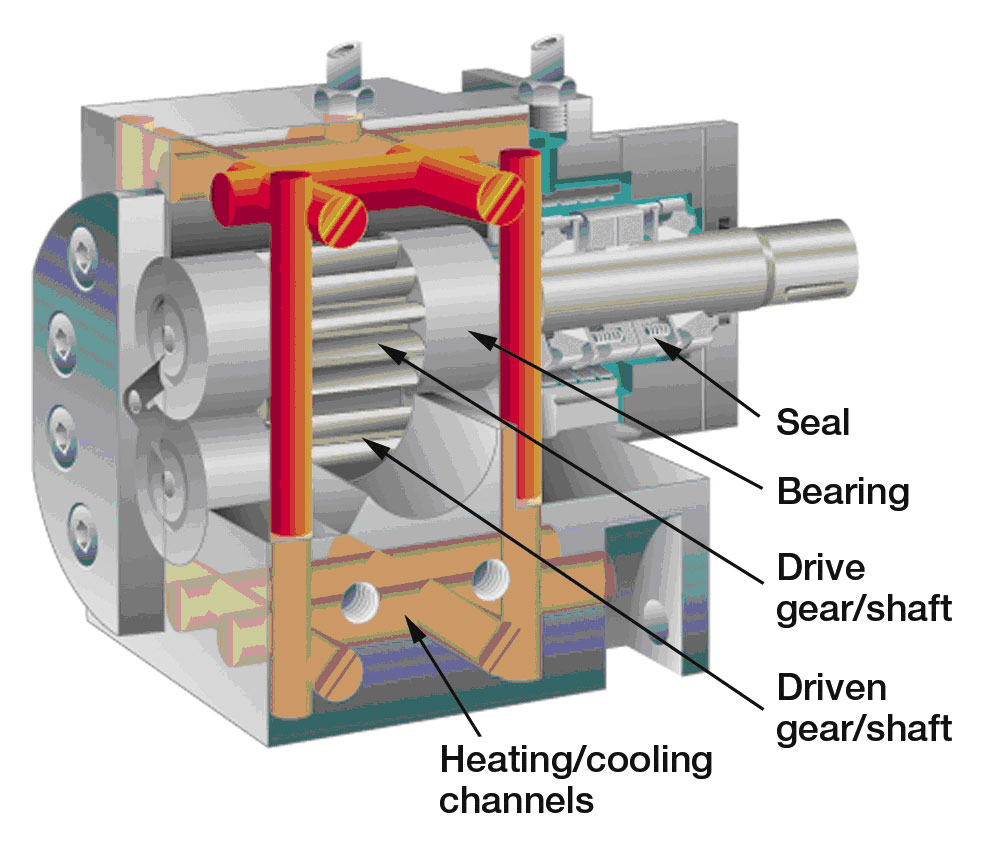
Figure 1. A jacketed gear pump.
There are three types of gear teeth in use: spur, helical, and herringbone. All three have advantages and disadvantages, depending on the application.
Spur gears are the simplest and offer the most benefit in high pressure applications. They produce no axial thrust and transfer the fluid efficiently from the suction side to the discharge side.
Helical gears produce slightly lower pulsations in the fluid stream, and are generally quieter running at higher speeds due to the way the teeth are gradually meshed and unmeshed. However, due to the axial thrust produced with helical gears, the differential pressures may be limited at lower viscosities depending on the bearing materials used. The thrust pushes the gear into the face of the bearing so higher pressures can only be achieved with hard bearing materials or specially designed surfaces which are able to handle this thrust.
Herringbone gears are essentially back-to-back helical gears. They offer slightly less pulsation than spur gears and axially balanced thrust. However, they are expensive to manufacture and assembly/disassembly can be difficult as they must be installed/removed as a set. In high viscosity applications, applications where the fluid solidifies, or in very large pumps, this is actually a big disadvantage.
The operation of an external gear pump is quite simple (see Figure 2). The fluid enters the suction side of the pump and is drawn into the opening cavities of the un-meshing gear teeth (Zone A). The fluid is transported in these cavities around the outside of the gear shaft to the discharge opening. The re-meshing gear teeth push the fluid out of the cavities into the pressure stream (Zone B).
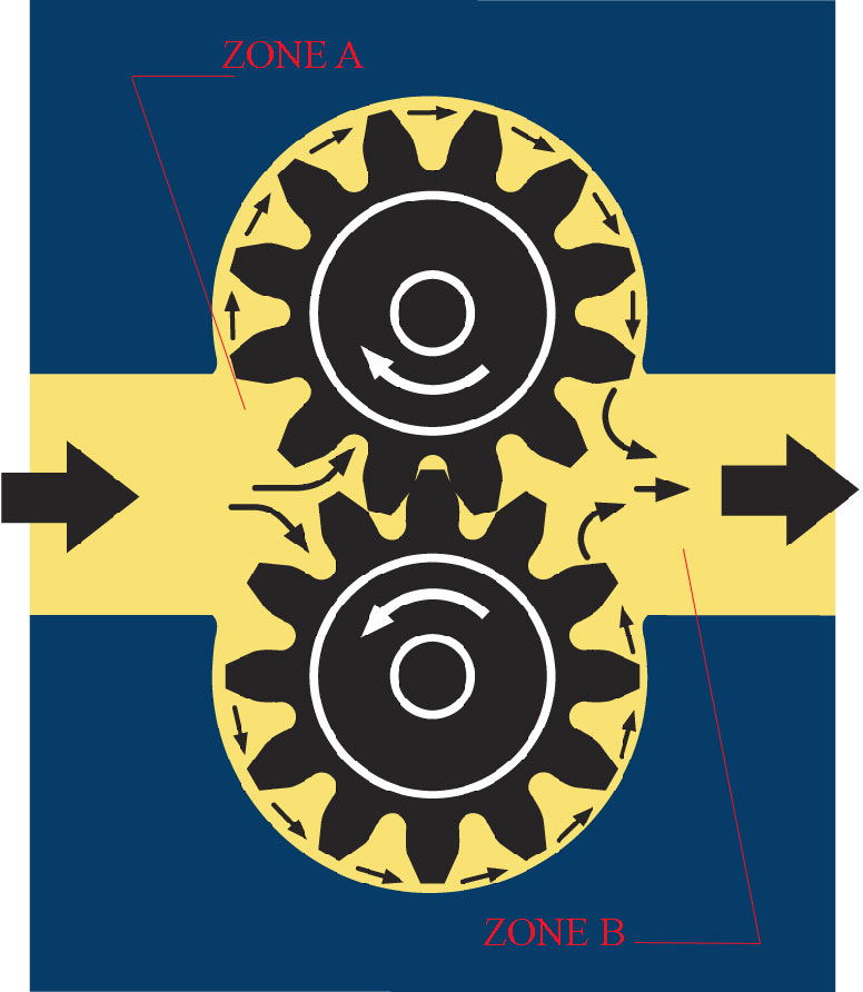
Figure 2. The operation of an external gear pump.
Theoretically, the flow rate in positive displacement pumps is independent of pressure. However, volumetric inefficiencies, or slip, are inherent in all types of positive displacement pumps. In order to achieve high differential pressures and the required flow rates, the gear pump must overcome this internal slip.
There are four main pathways of slip (see Figure 3): 1) between the gear shaft journal OD and the ID of the bearings, 2) between the gear faces and the bearing faces, 3) between the gear tips and the pump housing, and 4) between the meshing gears.
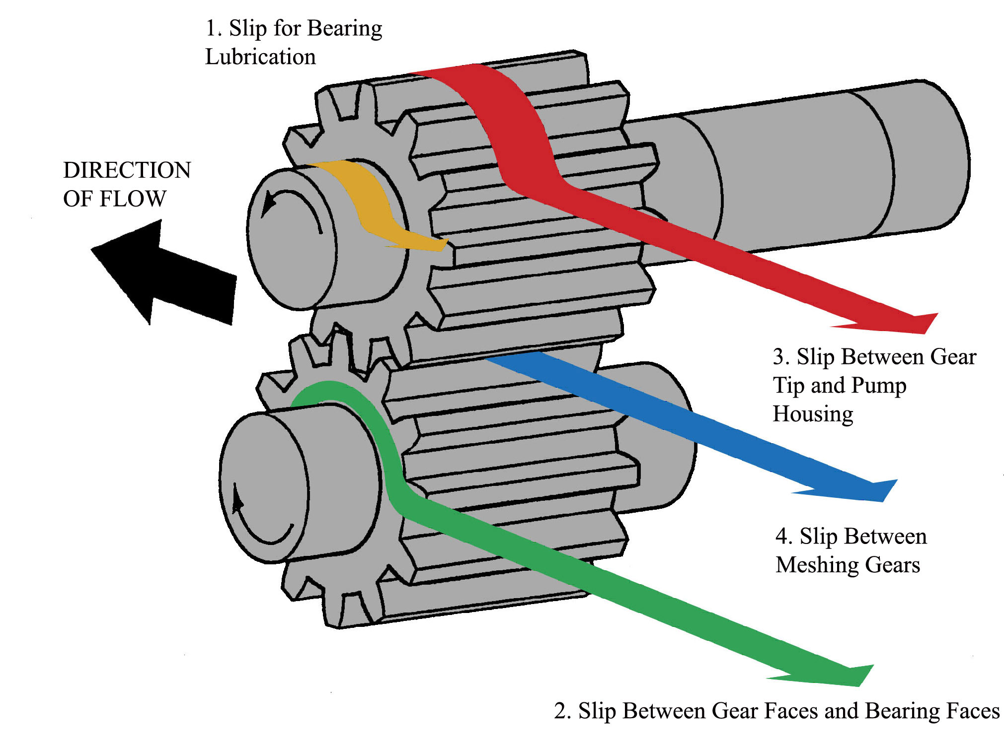
Figure 3. Slip pathways in an external gear pump.
To maximize the pressure capability of the pump, the clearances between the mating parts must be as small as possible to limit the slip. However, just tightening the clearances is not as simple as it sounds and consideration must also be given to other factors including temperature, viscosity, and material selection.
This is not to say that slip is all bad. In gear pumps, some slip is needed to lubricate the internal pathways and to hydrodynamically support the gear shafts in the journal bearings. In correctly designed gear pumps, this slip will account for 1 percent to 3 percent of the flow.
Material selection is very important in high temperature industrial applications. Gear pumps are often required to move fluids that are highly corrosive, abrasive, and/or reactive. The housing, shaft, and bearing materials first need to be compatible with the fluid being pumped. When you add high temperature into consideration, the pump design becomes even more complicated as different materials have different rates of thermal expansion.
As stated earlier, the internal clearances must be as small as possible to get the maximum pressure capabilities. In high temperature applications, due to thermal expansion of the components, the pump needs to “grow” into these exact clearances. This is a consideration that goes beyond what most commercial gear pump manufacturers can routinely offer. Overestimating the thermal expansion will make the pump clearances too loose and it won’t be able to create the pressure needed.
Underestimating the thermal expansion will cause the pump to seize and not turn when brought up to process temperature. For this reason, pumps built for high (or low) temperatures may not always function properly at temperatures they were not designed for.
For example, consider a pump housing made of 316 stainless steel with 440B stainless steel gear shafts and carbon bearings. 316 stainless steel has a rate of thermal expansion of 17 x 10-6 mm/mm/deg C, 440B is 11 x 10-6 mm/mm/deg C and carbon is 3.6 x 10⁻⁶ mm/mm/deg C. The pump manufacturer must have experience in dealing with these high temperatures and be able to calculate accurately what the pump clearances will be when the pump is at the process temperature.
Pre-heating the pump may be necessary in order to avoid thermal shock which can cause damage to the pump components. Pump preheating is generally recommended when pumping fluids at temperatures greater than 300-deg F. When using mechanical seals, the pump temperature should be within 90-deg F of the fluid temperature to avoid damage to the seal faces. Jacketed pumps heated with either steam or heating fluids and electric heating are the most common methods used for pump heating.
Viscosity is the resistance of the fluid to shear (or flow), so for high viscosity applications the first problem is getting the fluid into the pump. The pump must be turning slow enough for the fluid to fill the opening cavities of the un-meshing gear teeth. This opening cavity creates a suction which draws the fluid into the pump. The tighter the clearances, and the better the internal sealing of the pump, the more suction is created.
Once the fluid is in the pump, the internal clearances need to be correctly sized to accommodate the viscosity. Clearances that are too small will restrict the flow of the fluid in the pathways, leading to bearing overheating due to lack of lubrication. If they are too large, the fluid film strength collapses and it will not able to support and lubricate the shafts, resulting in journal-to-bearing contact and premature failure.
Another factor when dealing with high viscosity fluids is the torque required to turn the gears. The gear shafts must be of sufficient strength to transmit the torque from the driver. Gear tooth design is important because a gear tooth that is too large will not be efficient in moving the fluid and a gear tooth that is too small can fracture under heavy loads.
The torque on the gearshaft and the shearing forces on the gear teeth increase with increasing viscosity of the fluid and increasing differential pressure. Gear shaft and gear tooth design become especially important when these conditions are combined with high temperatures, as metallic components tend to weaken due to decreasing modulus of elasticity with increased temperature.
Pump applications involving high pressures, high viscosities, and/or high temperature take the user out of the realm of centrifugal pumps and into positive displacement pumps. As these conditions become even more extreme, and other types of PD pumps reach their design limits, the only choice left is the external gear pump.
While there are many manufacturers of external gear pumps, very few can handle these demanding conditions. It is wise for the user to look for suppliers who have experience with these demanding applications and who has a proven track record in successfully handling them.
Pumps & Systems, November 2006