


Q. What is the recommended instrumentation that should be used for measuring bearing housing vibration on rotodynamic pumps?
A. For all speeds, a 6-decibel per octave filter shall be used to filter out frequencies outside the measurement range to reduce the electronic noise. This filter is typically built into dedicated vibration data collection instruments. However, this filter may not be present when using software processing alone.
For speeds above 600 rpm, the measurement instrumentation shall be capable of measuring the RMS vibration velocity in a minimum frequency range of 5 to 1,000 hertz.
For pumps with speeds of 600 rpm and below, the measurement instrumentation shall be capable of measuring RMS vibration velocity and RMS peak-to-peak displacement in a minimum frequency range of 2 to 1,000 hertz.
The manufacturer and the purchaser should agree on the type of data collector and the data collector settings for frequency range, frequency resolution, filter settings, the number of readings to average and any other instrument settings that may affect the measured vibration values.
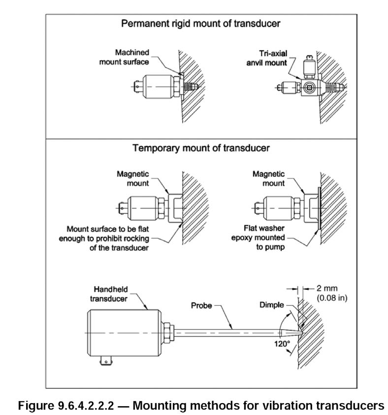
Personnel who conduct vibration tests should take precautions to eliminate sources of errors in the measurements that may be caused by transducer mounting, transducer cable lengths, transducer orientation, magnetic fields, temperature variation and sound fields.
The vibration transducers should be mounted in such a way that they do not adversely affect the accuracy of the measurements. If magnetic vibration transducers are used, the surface of the measured equipment should be prepared in accordance with the transducer manufacturer’s instructions at the point of contact to avoid measurement errors.
Appropriate mounting methods are shown in Figure 9.6.4.2.2.2. More information pertaining to vibration measurements can be found in ANSI/HI 9.6.4, Rotodynamic (Centrifugal and Vertical) Pumps for Vibration Measurement and Allowable Values.
Q. The expression NPIPR is used when discussing the characteristics of air-operated diaphragm pumps. What is NPIPR and what is its relationship to acceleration head?
A. The net positive inlet pressure required (NPIPR) is the amount of suction pressure required by an air operated diaphragm pump to obtain satisfactory volumetric efficiency and minimize damage from cavitation. This is usually when there is no more than a 3-percent reduction in the rate of flow (capacity) from the pump at any air inlet pressure and total head condition on the pump curve.
The pump manufacturer conducts a test to determine the NPIPR at the specified operating conditions. NPIPR is related to losses in the suction valves of the pump and the frictional losses in the pump suction manifold and pumping chambers. NPIPR does not include system acceleration head, which is a system-related factor and can be a significant problem as explained in ANSI/HI 10.1-10.5, Air-Operated Pumps for Nomenclature, Definitions, Application, and Operation.
Due to the reciprocating action of an air-operated diaphragm pump and the inertia effect of the liquid mass in the suction line, the pressure in the suction line is subject to fluctuation. This pressure fluctuation or acceleration head must be accounted for if the pump is to fill properly without liquid separation, pounding or vibration of the suction line. Acceleration head is the head required to accelerate the liquid column on each suction stroke so that no separation of this column in the pump or suction line occurs. If adequate acceleration head is not provided, the pump may experience cavitation resulting in the loss of volumetric efficiency. Damage is also possible from the force caused by the collapse of vapor bubbles.
The pressure required to accelerate the fluid column is a function of the length of the suction line, the average velocity in this line, the cycle speed, the design of the pump and the relative elasticity of the liquid and the pipe material. Additional details and a method for calculating the acceleration head is provided in the referenced standard, ANSI/HI 10.1-10.5.
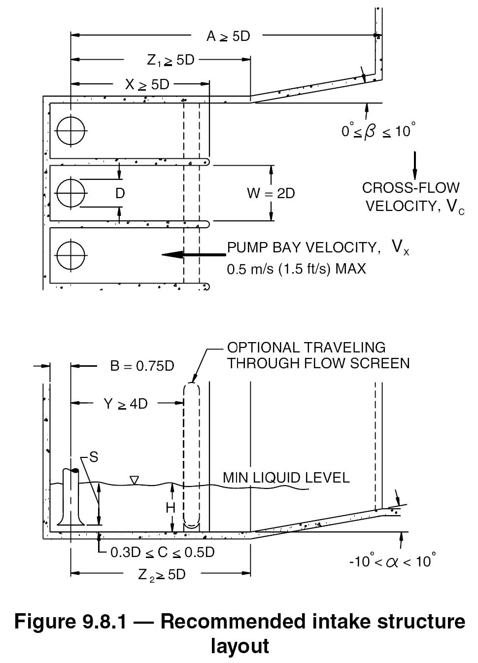
Q. What are some recommendations for dimensioning rectangular intake structures?
A. The design requirements for satisfactory hydraulic performance of rectangular intake structures include:
Adequate depth of flow to limit the velocities in the pump bays and reduce the potential for the formulation of surface vortices
Adequate pump bay width to limit the maximum pump approach velocities to 0.5 meters per second but narrow and long enough to channel flow uniformly toward the pumps
The minimum submergence, S, required to prevent strong air core vortices is based in part on a dimensionless flow parameter, the Froude number, defined as:
FD = V / (gD)0.5
The Froude number is a dimensionless quantity defined as a dimensionless grouping of parameters used in flow analysis and modeling that indicates the relative influence of inertial forces compared to gravitational forces. This equation is explained more thoroughly in ANSI/HI-9.8, Pump Intake Design.
The basic recommended layout for rectangular sumps, dimensioned in units of pump bell diameter “D,” is shown in Figure 9.8.1. The dimension variables and their recommended values as well as additional details are available in ANSI/HI 9.8.
Pumps & Systems, April 2012