Q. What is the preferred way to monitor corrosion in a rotodynamic pump?
A. Corrosion monitoring is an important aspect of maintaining a pump’s reliability due to the potential risk for failure and other negative effects that corrosion can cause. Corrosion monitoring is difficult, and proper materials must be selected to prevent or minimize corrosion. Based on study of corrosion rates, some systems may require the changes in materials as operating experience dictates. Choosing the appropriate materials for a specific service should be undertaken by knowledgeable corrosion engineers, and when done correctly, the necessity for corrosion monitoring can be reduced or eliminated.
Several different methods can be used to monitor corrosion. They are listed below with a short description about each method:
1. Visual/dimensional inspection—This method is the easiest and most economical monitoring method. Most forms of corrosion can be detected with it. However, some types of corrosion are not susceptible to visual signs, such as stress corrosion cracking. For the forms that can be detected using visual inspection, this method can reveal the degree of general corrosion occurring as well as signs of localized corrosion. Supplementing the visual inspection method with dimensional checks of key components can help calculate the amount of general corrosion that the pump is experiencing.
2. Electrical resistance (ER)—This method is based on the measurement of the increasing electrical resistance of a metal probe as its cross section is reduced by corrosion. If the probe is not the same alloy as the pump (for example, the probe is a wrought alloy and the pump components are cast alloys), there will be a small degree of error. ER probes are useful for determining general corrosion but not localized forms of corrosion, such as pitting.
3. Linear polarization resistance (LPR)—This method involves measurement of a current response to an applied potential through probes that are inserted in the system. A small known pulse of DC voltage is supplied to a test electrode and the resulting current is measured. The current generated is proportional to the corrosion rate, which can be determined by electrochemical principles.
4. Ultrasonic thickness measurement (UTM)—This method can be used to monitor corrosion on a periodic basis. However, it is not as accurate as other methods. This method is carried out by monitoring the change in metal loss per unit time at the same location over a period of time.
The ER, LPR and UTM methods lend themselves to continuous monitoring or frequent checks by use of small, portable data acquisition devices. The visual/dimensional checks are difficult to perform frequently because this method requires that the pump be shut down and opened to gather the data. The frequency of inspection using this method will then be determined by the importance of the pump. In the absence of experience, the first inspection with this method should be no longer than three months after the pump is initially put into service. Corrosion monitoring is also recommended shortly after any significant process or operational changes occur—such as temperature, concentrations or any changes in corrosives being handled, unless experience dictates otherwise.
Further information about each technique can be found in ANSI/HI 9.6.5 Rotodynamic (Centrifugal and Vertical) Pumps for Condition Monitoring.
Q. What is the recommended procedure for installing piston cups on a reciprocating pump?
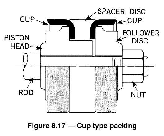
A. Piston cups are primarily used on piston heads, plungers or rams. They are used because of economical costs, excellent service life, efficient assembly, universal acceptance and simple accessories. More specifically, synthetic rubber piston cups operate continuously at high temperatures. These packing cups can be molded of synthetic rubber and other elastomers that resist strong acids and alkalies. An abbreviation of the recommended installation procedure for these cups is listed below (see Figure 8.17):
1. Ensure that no wear has occurred in the cylinder liner, and make sure that the cylinder liner and the packing cups are clean.
2. Lubricate the outside diameter of the surface of the packing cups.
3. Push the piston rod into the cylinder, and place the piston head over the piston rod.
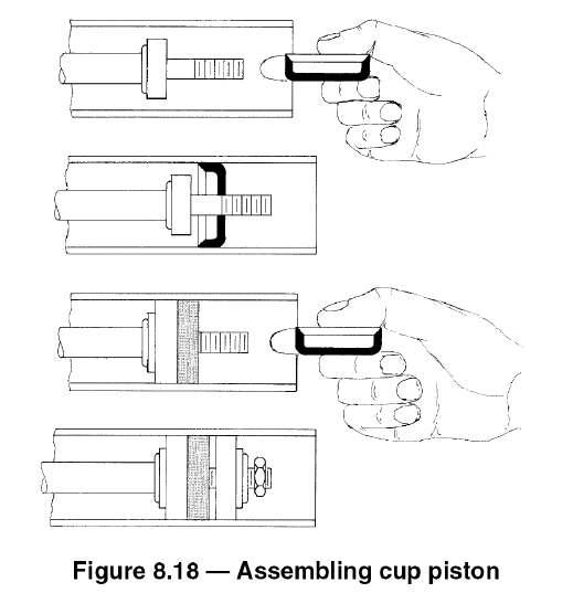
4. Insert the first packing cup, holding the cup horizontally until the lip has entered the liner (see Figure 8.18). Turn the cup to a vertical position, and lightly tap the cup into position over the hub.
5. Slip the spacer disc over the piston rod, and push it tightly against the first cup.
6. Insert the second cup, and use the same approach above to place the follower disc over the piston rod.
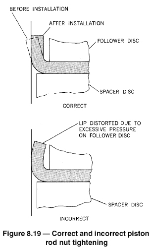
7. Apply and tighten the piston rod nut, making sure to not tighten it to the point where the cup becomes distorted, as seen in Figure 8.19.
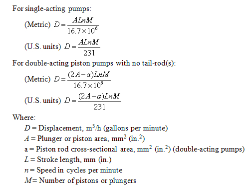
Q. How is pump displacement for a direct-acting reciprocating steam pump calculated?
A. The displacement of a reciprocating pump is the volume swept by all pistons or plungers per unit time. Deduction for piston rod volume is made on double-acting piston type pumps when calculating displacement.