


A green product means different things to different people. For some, a green product is alternatively powered, such as some of the recently introduced solar-powered well pumps. For others, green refers to products made from sustainable materials. In this article, green means a pump or pump system that uses less energy or reduces material usage in its design.
Pumps are often considered the second most common machine in the world after the electric motor. Billions are running in the world, bringing drinking water, disposing of waste and working in cars, buses, planes, power plants, process facilities, cooling systems, etc. With all of these pumps running in the world, even a relatively small increase in efficiency could result in a huge reduction in energy consumption.
Energy reduction in pump and pump systems can come from several areas. Most pump professionals would agree that the biggest potential energy reduction opportunities lie in the proper application and control of pumps with respect to the system demand. Simply, this means properly selecting and controlling the correct pump for the application. Many end users probably believe that their pumps run close to their best efficiency. In a relatively famous study, "Expert Systems for Diagnosis and Performance of Centrifugal Pumps," the Finnish Technical Research Center (www.vtt.fi) found that the average pump operates at less than 40 percent efficiency in the field, and 10 percent of pumps operate at less than 10 percent efficiency. The solution to many of these efficiency problems is not selecting a new higher efficiency pump or motor, but analyzing the pump system to ensure that the pump is properly sized for the application.
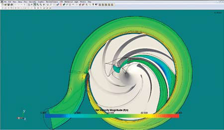
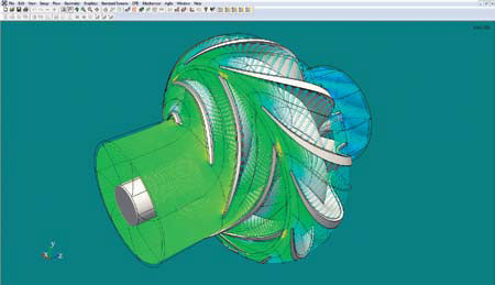
CFD of impeller and volute. Image courtesy of Concepts NREC.
Several free online system calculation tools allow even a novice user to input the components of his system with pipe sizes and generate a system curve showing the expected losses from the pump system. One such tool, Pump-Flo (www.pumpflo.com) from Engineered Software, allows the user to develop a system curve and then select from 85 different manufacturers to find a pump that matches the requirements.
What about pump manufacturers? If the majority of the potential energy savings lies with the pump's proper application, is room left to improve the products from the manufacturer's point of view? I routinely find clients with many underperforming pumps in their portfolios. These pumps are far below the efficiency of the competitive pumps in the marketplace. Modern hydraulic design tools can help the design engineers create and analyze pumps that can compete in the global market with higher efficiencies, lower Net Positive Suction Head Required (NPSHR) and better reliability.
Modern mechanical design tools allow the calculation of stress levels in complicated shapes and allow the designer to remove excess metal in lower stress regions while maintaining the needed structural strength in others. This leads to less material usage, lighter components and less-expensive component costs. By combining these two initiatives, many pump companies can use these new tools to lower costs while providing a greener, more competitive product.
Modeling the Impeller
The impeller is the only element in the pump that adds energy to the liquid. Maximizing the amount of energy transferred into the liquid is the most crucial step in the improvement of a pump's performance and its efficiency. Traditionally, designers would manipulate the inlet and outlet widths and radii to achieve reasonable velocities and vane angles at the inlets and outlets of each pump component. Once the inlet and outlet angles were determined, the shape of the blading in-between was often determined more by art than science. Some designers used a linear angle change from inlet to outlet; others shaped the vane based on a logarithmic spiral. While these techniques produced many good pumps with excellent performance and high efficiencies, in too many others the lab results often fell short of expectations. This design technique relies heavily on the designer's feel and experience. If the designer was too aggressive with the change in angle, the impeller would end up with short vanes that were often incapable of guiding the fluid or imparting the required amount of energy. A less aggressive designer might change the vane angle at a lower rate, resulting in a long vane passage that increased the friction and reduced performance and efficiency.
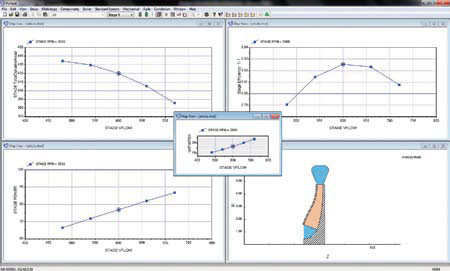
Meanline pump analysis. Image courtesy of Concepts NREC.
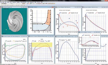
Streamline curvature analysis of pump impeller. Image courtesy of Concepts NREC.
With the new design tools available today, we no longer have to stumble blindly through the design to determine a pump's proper blade profile. The ability to see into the vane passageways of a spinning
impeller and predict the path, velocities and pressure of the fluid moving through them provides an enormous opportunity for product improvement. Looking into the vane passages can be done by using a couple techniques. The first is through the use of streamline curvature calculations to predict the properties of the flow along discrete streamlines through the pump. Using multiple streamlines throughout the passage, the designer can estimate the velocities along the blade surfaces at multiple locations and produce an accurate profile of the flow properties. This provides feedback on blade loading, blade incidence angles and areas of possible stall or separation. The best part is that the feedback is nearly instantaneous, generally less than a few seconds of calculation time, allowing the designer to try multiple tweaks to improve blade loading, incidence and overall stage performance in a short amount of time.
When the stage appears to the designer's liking, the next step is to run the stage through a Computational Fluid Dynamic (CFD) analysis. Since we cannot implicitly solve the flow path as a continuous domain, this technique breaks the passageway down into a mesh of small blocks that a computer can solve iteratively. By solving all of the flow equations at each node point, we get a detailed prediction of the velocities, pressures and temperatures at each block. This allows the designer to verify the performance predicted by the initial meanline design or possibly show areas that could be improved before another CFD run.
CFD comes in many forms. Some codes are general purpose and use random, unstructured meshes. These meshes generally use the size of a feature to create the mesh around it, so short lines create high mesh densities, often in areas that are unimportant to the fluid's actual flow. These general purpose tools work well for stationary elements of the pump, but often struggle to deal with the interface between moving and non-moving parts. They also often require the entire pump to be modeled, resulting in enormous mesh sizes that take a considerable amount of time to run. Several codes have modules built specifically for turbomachinery analysis, and most of these use a structured mesh that allows the designer to solve only one blade passage of the pump. This drastically reduces the number of elements needed for the model, so more elements can be placed in areas of interest, and run times are much shorter. The results are often more accurate.
Relative velocity vector plot of a vertical turbine pump stage. Image courtesy of Concepts NREC.
Beyond the impeller, CFD can be used to make drastic improvements in the stationary passages within the pump. Complex inlets for pumps like vertical in-lines or double suction horizontal split case pumps are extremely difficult to design without significant testing or the use of CFD. Many of these designs distort the flow into the impeller so much that they cause major reliability and efficiency problems, especially at off-design operating points. On one client design a few years ago, we redesigned the inlet of a vertical inline pump and improved the overall efficiency by 12 percent. The same logic applies to the pump's discharge side. I recently changed the volute tongue angle and exit bend radii on a top centerline discharge pump design and improved the efficiency of the unit by 3 percent.
On the mechanical side of the design, some of these pump design packages have tools to help the designer evaluate the strength and rotordynamic properties of the stage. Tools such as finite element analysis (FEA) have opened a new world in structural analysis. These tools allow for the rapid determination of stress levels, thermal growth and natural frequencies of pump components and the entire stage.
Some of the top-of-the-line packages have mechanical analysis tools built into the software. Tools such as Campbell plots, Goodman diagrams and pre-FEA processing tools allow the designer to initially look at the pump's stress levels and vibratory modes without the time and expense of running a full 3-D finite element analysis on the stage. These tools, like the streamline curvature tool for hydraulic development, allow the designer to quickly try and analyze many different design options before the stage is passed on to a full 3-D FEA, which may take longer to complete. Additional tools such as FEA preprocessing and preconditioning also accelerate the creation of the FEA model. The ability to automatically map the CFD-predicted pressure forces onto the pump's surfaces can save hours of time in developing pressure distributions within the FEA software. The ability to add features such as fillets and balance holes while still in the design package also speeds the development of solid models, as well as FEA model set-up time. Using a combination of the tools mentioned above, the author has reduced the material weight in several pump designs by 305, allowing for a major reduction in material usage and overall product cost.
These modern analysis tools give pump and system designers the opportunity to greatly improve the efficiencies of their pumps and the performance of overall systems. Even a small increase in the overall efficiency of these units would mean a drastic reduction in energy usage and lower pumping costs for the end user.
Pumps & Systems, August 2010