


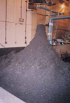
Recessed impeller pumps are a solution for grit transfer in wastewater and water treatment applications.
Grit is highly abrasive. Selecting pump materials of the correct construction and hardness is critical to ensure long pump wear life. For wastewater treatment plants, grit is typically defined as an “inorganic solid,” and it can be made up of sand, gravel, cinder, glass and other heavy inorganic material. The major abrading component of grit is silica sand. As a guide, the typical hardness of silica sand is in the Brinell harness number (BHN) range of 570 to 590. For water treatment plants, where the water source is a river, similar solids will enter the plant during higher river flow rates, which can increase water turbidity.
The amount of grit entering these plants varies. However, both facilities must remove it as soon as possible to alleviate erosive wear as the process water moves through the plant for treatment. Grit removal systems are provided in many different forms, and all require pumps for the disposal of the inorganic solids.
Design Requirements for a Grit Pump
With grit (silica sand) being so abrasive, what is paramount in selecting an appropriate pump is its ability to stand up to erosive attack. Historically, the design of choice has been a recessed-impeller or vortex centrifugal pump. This style offers the benefit of operating without the requirement of close impeller clearances, being available in hard metal construction and having performance minimally impacted when wear occurs. These all add up to long pump life.
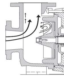
Two basic styles of recessed-impeller pumps are available, radial vane and cup type. Both designs have been used in grit/slurry applications for more than 30 years and are industry proven. They are offered in hard metal construction with extra thick wet-end components. The difference in their wet-end designs is ultimately dictated by the hydraulic flow path through each pump, which in turn dictates where the brunt of the wear will occur. For true, recessed-impeller pumps it is expected that roughly 80 to 85 percent of the flow through the pump will not come in contact with the impeller. The distinguishing factor between the two designs is where the flow that does come in contact with the impeller is directed.
For a radial vane design, this flow will be directed out to the impeller periphery making this area the predetermined point of wear. For true heavy duty radial vane recessed impeller pumps, the casing will not suffer this wear as it is protected by an independent heavy duty peripheral wear plate assembly.
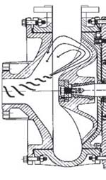
With this pump design, wear does not occur at the suction area of the casing so a single piece casing is used. In contrast, for a cup-type design, the flow that comes into the impeller gets directed back to the suction of the pump by the impeller's cup profile, making this area the predetermined point of wear. The casing is, therefore, provided in two pieces so that the end user does not have to replace the entire casing when this area wears.
With both designs, key requirements must be met, such as:
- The pump's wet-end materials of construction must be harder than the hard abrasive
- Thick wet-end components (those items coming in contact with the fluid)
- Must have a sacrificial component so that the entire casing does not have to be replaced
- Keep pump and tip speeds down to acceptable level
Materials of Construction
First, and foremost, is having the pump wet end manufactured from a material harder than the hard abrasive. Historically, this has been Ni-hard (ASTM A532 Class 1). Ni-hard is a nickel/chromium (Ni-Cr) cast iron. This material's microstructure reveals an iron carbide precipitate in a matrix of primarily martensite with some austenite.
The combination of carbides and martensite provide an excellent combination for resistance to low- and medium-stress abrasion. Standard sand cast Ni-hard will have a BHN of 550 to 650. For grit service where the maximum hardness of silica sand can exceed the minimum hardness of standard Ni-hard, extra steps must be taken to push the Ni-hard BHN even higher. This is achieved by modifying standard Ni-hard through a cryogenic process to increase both hardness and toughness. The freezing of the sand cast material converts a large portion of the retained austenite to martensite increasing the hardness to a BHN range of 650 to 700.
Thick Wet-End Components
Typically, grit flow rates fall into the 150 to 300 gallons per minute range resulting in a 3-inch or 4-inch pump selection. Recommended minimum volute thicknesses are 9/16 inch for 3-inch pumps and ¾ inch for 4-inch pumps. Wear plates/suction pieces for each respective design will be 1 inch or greater for 3-inch pumps and 1¼ inches for 4-inch pumps. The impeller designs are different but will have vane tip thicknesses in the 3/8-inch to ¾-inch range.
Sacrificial Components
As previously indicated, the position of these components is dictated by the hydraulic flow path through each respective pump design. The responsibility of these components is to eliminate the need to replace the casing in its entirety due to wear. For a radial vane design, this comes in the form of a peripheral wear plate allowing for a single piece casing (back plate is separate). For the cup-type design this comes in the form of a suction piece as well as a peripheral wear plate (when the rim of the impeller wears sufficiently flow will be directed to the periphery) resulting in a two-piece casing. The back plate is separate.
Low Pump Operating Speeds
The goal is to keep the pump operating speeds as low as possible targeting tip speeds below 5,300 feet per minute (note typically for grit applications pumps are operating with tip speeds below 4,000 fpm). This is ultimately dictated by the total dynamic head (TDH) requirement upon the pump and whether it is in a direct-drive or V-belt-drive configuration. Note that hard metal slurry pumps for abrasive mining applications will allow tip speed operation as high as 5,300 feet per minute for up to 30 percent solids by volume so the above criteria are conservative.
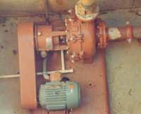
Mounting Configurations
Typically, grit pump installations require that the pump be mounted in a dry pit with a horizontal drive configuration. This arrangement will provide the most robust foundation and allow for the easiest maintenance and operation. Given that hard metal construction is being used, the pumps will traditionally incorporate a full-diameter impeller and will meet specific hydraulic conditions through a V-belt-drive arrangement. The motor can either be mounted on the side or in elevated configurations (Z-mount or over-head, for example).
In some cases, a wet pit installation is favored, typically due to spatial constraints within the plant. When this is the case, the most common configurations available are either a vertical cantilever or submersible pump arrangement. For vertical cantilever pumps, the pump setting (distance from base plate to the casing suction flange) is most often limited to 72 inches, and a suction tailpipe is added to position where the flow is drawn.
Sealing Arrangements
This is dictated by plant preference, but historically, the dry pit pumps will either be supplied with a packed stuffing box or a commercially available single mechanical seal incorporating hard faces (silicon carbide or tungsten carbide). With both sealing options, a clean, pressurized water flush is required. For vertical cantilever pumps, no seals are required, and for submersible pumps, a tandem seal arrangement with a hard faced lower seal is used.
Conclusion
Clear guidelines for selecting an appropriate grit pump have long been established, and there are proven pump designs in the market. The greatest concern facing clients now is with some manufacturer's sourcing substandard wet-end material (i.e. 600 BHN or less) off-shore. There are a multitude of North American foundries providing suitable 650 BHN minimum hard metal materials, and this must remain the standard. Any material hardness less than this is unacceptable for ensuring long, reliable component life.
Pumps & Systems, October 2011