


A “stable” curve is important for pump operation, especially for pumps in parallel operation. The higher the energy level and the more critical an installation, the more the pump curve could become an issue. API 610 even states that “…pumps that have stable head/capacity curves (continuous rise to shutoff) are preferred for all applications and are required when parallel operation is specified. When parallel operation is specified, the head rise shall be at least 10 percent of the head at rated capacity.”

Figure 1. Stable (left) and unstable (right) H-Q curves
Centrifugal Pump Curves
A centrifugal pump operates at the intersection point of a pump curve and system curve. A system curve is a parabola, starting from zero in the case of mainly friction losses (long pipe with restrictions, such as valves, fittings, etc.), or a parallel line in the case of mainly static heads (pumping up to a vessel). It can also be a combination of both.

Figure 2. A pump operates at the intersection of a pump H-Q curve and system curve.
If the pump curve is stable, a unique point (A—an intersection of a pump curve and system curve) always exists. See Figure 3. If the pump curve is unstable, the region between Point B and Point F has two possibilities—at either flow Qb or Qf.
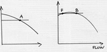
Figure 3. The stable curve (left) has a single, defined intersection between the pump curve and system curve. The unstable curve (right) has two flows at which a pump can operate at the same head.
Pumps in Parallel Operation
Imagine a parallel operation with two pumps piped to a common header. Suppose Pump 1 (P1 in Figure 4 on page 22) is running and Pump 2 (P2) is idle but ready to be brought online. Starting a pump is usually done near the shutoff with the valve slightly cranked open to minimize motor load. If P1 is running in an odd region, perhaps Point C (where the curve is unstable), the system head is Hc and, therefore, higher than the shutoff head (Hf), which is what P2 will generate when it starts. Therefore, P2 cannot open the check valve, which is held closed by the higher pressure (Hc) that is in place because of the already-running P1.

Figure 4. Two pumps in parallel—P2 has trouble starting
Now, imagine that several pumps are running in parallel, as illustrated in Figure 5 on page 22. Since they discharge to a common header, their discharge head must be the same. However, each pump may have different flows—either Qc or Qe, as shown in Figure 5. If a plant operator needs to increase the total flow and opens the discharge valve more, P1 will increase its flow, and its head will decrease (Qcc, Hcc). The new system head (Hcc) will now push P2 to a lower flow (Qee).
Eventually, a stronger pump may completely take out the weaker pump at the shutoff head or near it. The operator, only noticing a total increase in flow, may not even know what has happened. P2 then unexplainably begins to vibrate, shake and possibly fail.

Figure 5. P1 is forcing P2 out, not an ideal situation.
An excellent reference on this subject, with a more detailed explanation of unstable curves, is “Centrifugal and Axial Flow Pumps” (a book by A.F. Stepanoff, John Wiley publication, 2nd Edition, page 293). In this book, Stepanoff defines the conditions needed for the curve to be unstable:
- The mass of water must be free to oscillate, a typical scenario in boiler feed applications.
- There must be a member in the system that can store and give back the pressure energy or act as a spring in a water system. In a boiler feed pump cycle, the elastic steam cushion in the boiler also serves the same purpose. Long piping can also do the same.
Stepanoff also provides these recommendations:
- Bypass part of the capacity to the suction supply tank
- Add an automatic capacity governor near the boiler, with slight throttling at the pump to stop H-Q swings
- Brace piping, except for the provision for heat expansion
- Avoid operating near the critical point
Pumps With Higher Specific Speeds
For higher specific speed pumps, such as axial flow pumps, the instability happens at flows substantially closer to the best efficiency point (BEP), as compared to lower specific speed pumps (such as boiler feed pumps). However, this instability is local, and the curve continues to rise again after the local region of instability.

Figure 6. High specific-speed pumps have instability starting much closer to BEP as compared to lower specific speed units.
Balance Is Key
It is true that the “best” designs with regard to efficiency often end up with unstable curves. Such is the nature of the hydraulics of pumping machinery. A better and more practical compromise is not to push the efficiency overly high at a single BEP but to have a more balanced design, with overall good efficiency and a stable curve. This is because, in practice, it is almost impossible to limit a pump operation to a very near region of flow.
All pumps, regardless of their energy levels, may experience curve instability. As a practical matter, small pumps, however, such as inexpensive commercial units or even small pumps for chemicals, such as ANSI, usually either do not operate in parallel often or, if they do, they can be started with a more open valve. Since the energy level is small enough and the duration is short (when compared to more powerful units—such as boiler feed pumps and circulating vertical pumps), a problem seldom occurs with these pumps, but it can happen.
A note to the readers: We welcome any additional comments on this subject. If anyone would like to expand or add a personal experience regarding curve instability and practical ways of handling it, please let us know so that we can add your contribution to the next issue of Pumps & Systems.
Pumps & Systems, February 2011