


Temperature changes can push pipe force beyond safe limits
To view all of the articles in the Thermal Stress Affects Pipe Forces on Pump series, click here.
Two major headaches for pump plant maintenance are seals and bearings. While new bearings or seals being faulty is always a possibility—although not typical if purchased from a reputable manufacturer—this is not the main reason for failures. A more likely reason is either a bad installation or improper operation. In this article, we will discuss installation.
Minimize Pump Forces
The main objective of a good installation is to minimize the forces that act on a pump. If a pipe bumps into a pump, it will force the casing to deflect in relation to the rotor. A stationary portion of a seal sits within the gland—essentially a part of the casing—while the rotating portion of a seal sits on and rotates with the shaft.
A similar situation applies to the bearings when a motor shaft is “forced” to align itself with the pump shaft. Therefore, any significant relative motion between the rotating shaft and the stationary casing boundary is likely to cause their failure.
API-610 specification has a table that contains the maximum allowable forces and movements as a function of pump size. A bigger pump can withstand somewhat higher piping force than a small pump. However, the intent of these tabulated allowable forces does not allow for sloppy installation. Piping to casing nozzles must still be aligned with free-bolt condition which means that bolts should not be forced but freely inserted between flanges.
Therefore, there should be essentially zero force exerted onto the pump by the piping. If this is not the case, then the piping needs to be cut and reconnected—an unfortunately expensive but necessary step if end users are interested in reduced bearing and seal failures.
Thermal Forces
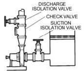 |
| Figure 1. Pump attached to cold water tank |
The allowable forces tabulated in API-610 and in similar ANSI pipe loading criteria and other specs—such as PIP, for example—are meant to apply to thermal changes, which are not within the control of the installing maintenance/millwrights crew.
This requires piping designers to make sure proper expansion loops, hangers, supports and other factors are considered so that the incremental forces due to thermal changes are within the tabulated specified allowable forces and will not damage the pump. Pump designers, therefore, ensure that the pump is designed robustly enough to withstand these forces.
Case Study
To illustrate, consider a simple example of a pump connected via a short pipe (2 feet long) to a storage tank with clean cold water. See Figure 1.
Let's assume the water in the tank heats up from 60 degrees F in the morning to 90 degrees F in the summer afternoon. With a pipe, cross-sectional area of roughly 10 in.2 (which is typical of an 8-inch pipe), the calculation below shows relative and absolute pipe elongation for carbon steel pipe as it is heated by the water and the stress caused within it by the elongation restricted by a pipe jammed by thermal expansion strain between the tank and a pump:
ΔL/L = = αΔT = (6.9 x 10⁻⁶ in/in°F) x 30° = 0.0002 in/in
ΔL = LαΔT = (2' x 12") x 0.0002 = 0.005"
stress σ = E ΔL/L = (30 x 106) x 0.0002 = 6000 psi
Force = 6,000 lb. x 10 in.2 = 60,000 lb.
L = Pipe length
ΔL = Change in pipe length
ΔT = Change in temperature
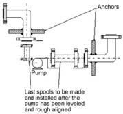 |
| Figure 2. Anchors are a bad idea because they result in high loads. |
This force far exceeds every possible API-610 allowable force or any similar specification. For a longer pipe, this situation would obviously get even worse.
A “natural” inclination is to grab a pipe in front of a pump, isolating it from the rest of the pipe, essentially shortening the effected growth in front of the pump. This would “seem” like a good idea for hot processes in which temperature changes could be even greater than this example.
Such “natural” thinking is not a good idea, as the anchors created will result in high loads—as shown in the calculations above. The only correct approach is not to use anchors.
Use sliding supports, and design the entire piping in such a way that the expansion does not cause the movement of the pipe ends—neither toward the pump or toward the tank. That is also not an easy task, but we will leave that challenge to the piping designers and plant process engineers.
From the pump standpoint, all we ask is no forces on pumps, please.
January Quiz
Now, a parting quiz/question:
What is wrong with the calculated 60,000 lb. value from the case study calculation? Can it be true?
A correct answer gets you a winning ticket to my next hands-on Pump School training session: www.pumpingmachinery.com/pump_school/pump_school.htm.