


Pumps & Systems, October 2008
Q.
What is a free standing baseplate and when should it be used? Are there any special design requirements?
A.
A free standing baseplate is designed to properly support a pump and driver and intended to be elevated off the floor, and supported by stilts, shims or springs. This type of baseplate must be designed to provide its own rigidity, as there is no grout for additional support.
The features of a free standing baseplate are:
The purpose of a baseplate is to provide a foundation under a pump and its driver that maintains shaft alignment between the two. This baseplate must allow for initial mounting and alignment of equipment, survive handling during transportation to the installation site, be capable of proper installation with minimum difficulty, allow final alignment of the mounted equipment and allow removal and reinstallation of equipment. Note that it is not necessary that an absolutely rigid baseplate be designed to meet these requirements. At the same time, the baseplate must not be permanently deformed after the equipment is mounted at the manufacturing facility. Compliance with these design criteria, in conjunction with proper installation procedure, will contribute significantly to meeting the functional requirements.
A free standing baseplate must be rigid enough to maintain coupling alignment when subjected to loads from piping or motor torque. The rigidity shall prevent no more than 0.25-mm (0.010-in) parallel coupling misalignment and 0.005-mm/mm (0.005-in/in) angular misalignment when subjected to maximum motor and piping loads simultaneously.
For additional information on baseplate design, see ANSI/HI 1.3 2007 Rotodynamic (Centrifugal) Pumps for Design and Application.
Q.
Do rotary pumps have the same problems as centrifugal pumps when pumping liquids with entrained air or gas?
A.
Yes and no. Yes, rotary pumps have a similar problem when pumping liquids with entrained gas. The gas displaces an equal volume of liquid, which reduces the rate of flow from the pump. The problem is further aggravated if the inlet pressure is reduced before the mixture enters the pump. Figure 3.29B shows how the rate of flow is reduced further when the actual inlet pressure is very low.
Note from Figure 3.29B that at 3-in mercury absolute inlet pressure, 5 percent gas at atmospheric pressure will reduce the rate of flow to about 60 percent. ANSI/HI 3.1-3.5, Rotary Pumps for Nomenclature, Definitions, Applications, and Operation includes more information on this subject.
No, the good news is that rotary pumps do not become airbound like centrifugal pumps. There is no centrifuge effect in a rotary pump and if the rotating parts are wetted, the pump can displace large amounts of gas.
Q.
I understand that vertical can pumps can operate with very low values of NPSH available, such as on condensate service. What is a vertical can pump and how does it work with such low NPSHA?
A.
Vertical can pumps are vertical turbine pumps mounted in a can as shown in Figure 2.64.
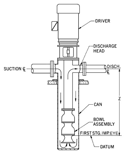 They can operate with low NPSHA by taking advantage of the additional submergence in the can as measured by the distance Z.
Vertical can pumps are also effective for booster service in surface piping systems due to the in-line arrangement of suction and discharge connections. The drive, normally a vertical induction motor, is mounted directly on top of the pump. Either a vertical hollow shaft or solid shaft motor may be used. Solid shaft motors are preferred for this type of application. Horizontal drivers such as engines or steam turbines may be used in conjunction with a right angle gear drive to transmit torque to the pump.
For a successful installation, place special emphasis on proper sump (inlet) and can design. The materials of construction should be selected based on the service requirements. To avoid cavitation, submerged vortexing, surges or other flow instabilities, incorporate the pump manufacturer's published standard dimensions in the system design. Additional information may be found in ANSI/HI 9.8, Pump Intake Design.