


Editor's Note: This is the third in a series of five articles based on the Hydraulic Institute's new Positive Displacement (PD) Pumps: Fundamentals, Design and Applications e-Learning course. To read the previous article, click here. To read the next article in the series, click here.
Last month, we introduced Module 2 of the course, which focused on Positive Displacement Pump Hydraulics. In this issue, we will focus on Module 3, "Rotary Pumps" (see sidebar for more information). This article will provide an overview of the common characteristics of rotary pumps, the rotary pump types within the rotary pump family, and the application analysis and pump selection process.
Rotary Pump Overview
Rotary pumps are available in a broad range of flow and pressure, which is why they are recognized by users as the solution for their specific pumping needs. Recent enhancements have increased the reliability and operating envelopes of rotary pumps. They are increasingly recognized for their efficiency in today's energy conscious environment.
A rotary pump typically consists of a stationary pumping cavity containing rotating pumping elements that are actuated by the rotation of the drive shaft. This rotary motion is the distinguishing feature of this class of pumps-hence the name rotary pump. The pumping elements are characterized by close fitting running clearances. Rotary pumps have no need for separate inlet or outlet valves.
Rotary pumps are designed so that the rotating pumping elements draw the fluid at the suction port into the pumping cavity, transport it through the pumping elements and force it through the discharge port into the system.
The geometry of the pump elements and pumping cavity determine the volume of fluid pumped per revolution of the shaft. This volume is called the displacement. Most rotary pump types are configured for fixed displacement; however, they can produce variable flow rates by varying the shaft speed. Vane and piston rotary pumps produce variable volume by changing the internal geometry (i.e., varying the displacement of the pumping elements).
Rotary Pump Types
The most common types of rotary pumps and their subcategories are shown in the rotary pump tree (Figure 1). This module presents the basic pumping principle for each type of rotary pump, typical configurations and major components, range of performance and operating capability, location in the overall rotary pump spectrum, application characteristics, features and benefits and typical applications and industries served.
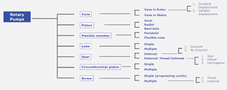
Figure 1
Vane-in-rotor pumps are characterized by moveable vanes, or rigid blades, retained (but not necessarily fixed) by an eccentric rotor that rotates within the pumping cavity. This action draws fluid in and forces fluid out of the pumping chamber, thereby delivering flow. Vane pumps can be either fixed or variable displacement.
In rotary piston pumps, fluid is drawn in and forced out by multiple pistons that reciprocate within cylinders in the cylinder block, producing flow. There are two basic types: axial and radial piston. Both types are available as fixed and variable displacement pumps.
Flexible member pumps transfer the product from the inlet to outlet by making use of the elasticity of the flexible member(s). The flexible members may be a tube, vanes or a liner.
Lobe pumps carry the pumped fluid between rotor lobe surfaces and the pumping chamber from the inlet to the outlet. In this regard, they are similar to gear pumps but do not produce the shear effects. Timing gears are used to coordinate the motion of the lobe surfaces, avoid surface contact and provide continuous sealing.
Gear pumps carry the pumped fluid between gear teeth and displace it when the gears mesh. The surfaces of the gears cooperate to provide continuous sealing, trap pockets of the pumped fluid and push it out the discharge port. One of the gears drives the other idler or driven gears. There are two main variations-external and internal gear pumps.
Circumferential piston pump rotors are timed and each rotor has one or more wing lobe elements, called pistons. There is no sealing contact between the piston surfaces.
Single-screw pumps (commonly called progressing cavity pumps) have a rotor with external threads and a stator with internal threads. The geometry of the rotor and stator form cavities that progress from inlet to outlet as the rotor rotates, which creates the pumping action.
Multiple screw pumps are divided into two broad families-timed and untimed. Typically, multiple screw pumps have two or more intermeshing screws and the flow is in the axial direction. The inlet fluid, which surrounds the rotors, is trapped as the screws rotate. With the rotors in tight fitting bores and the casing acting as a stator, the fluid is moved uniformly with the rotation of the rotors along the axis and forced out at the other end.
Application Analysis
The application analysis stage is a vital step in the pumping solution process. Rotary pump application benefits from careful attention to the performance requirements of the system. This process determines initial affordability, flexibility to cover the entire operating range of the application, reliability and energy efficiency. It is important that the purchaser/user understand, identify and communicate the requirements to the pump supplier.
A recommended sequence is to first consider the characteristics of the fluid(s) to be pumped (A), then the operating conditions the process requires (B), and finally the resultant hydraulic requirements of the system (C) (see Figure 2).
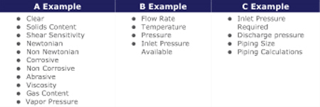
Figure 2
Self priming is an important advantage rotary pumps have over rotodynamic pumps. There is considerable variation in suction capability among rotary pump types due to the design of the pumping elements and the inlet configuration. It is important to remember that the fluid to be pumped is pushed into a pump by the pressure differential available at the pump inlet. Therefore, special attention should always be focused on inlet conditions. Users and system designers are always well advised to make sure the Net Positive Inlet Pressure Available (NPIPA) from the system exceeds Net Positive Inlet Pressure Required (NPIPR) by the pump and includes a reasonable margin.
Because a rotary pump will deliver an essentially constant volume of fluid per shaft revolution regardless of system pressure, it is necessary when applying rotary pumps to provide protection against over-pressurization in the event of a system malfunction.
Pump Selection
Delivered flow from a rotary pump is dependent on its displacement per revolution, speed of operation and slip flow. Even though rotary pumps are characterized by close internal clearances, there will be some leakage between high pressure outlet and low pressure inlet areas within the pump. This leakage is called slip and may be large or small depending on the type of rotary pump, the fluid characteristics and the operating conditions.
Rotary pump input (brake) horsepower requirements vary as a function of the pump type and operating conditions in each application. Input power is the sum of the power required to move the theoretical flow volume of the pump against differential pressure plus internal power losses. Internal power losses occur because it is necessary to overcome mechanical friction from the moving parts of the pump and the viscous drag effects and shearing of the pumped fluid.
With many types of rotary pumps available, selection of the proper pump for the application may seem complex. The pump selection process involves matching the properties of the pumped fluid, operating conditions, and system requirements identified in the Application Analysis with a pump's capabilities. The performance capability of the rotary pump selected must be verified over the full range of required operating conditions.
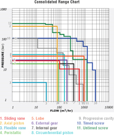
The Rotary Pump Module provides two useful tools to help narrow the choice of rotary pump types (reproduced in Figures 3 and 4):
A Consolidated Range Chart where the flow and pressure envelope of each rotary pump type is depicted (see Figure 3). With knowledge of the full range of flow and pressure requirements of the application, suitable rotary pump types can be identified on the range chart. Consultation with the supplier is recommended to confirm specific application recommendations and to investigate special designs, which are often available to provide unique solutions.
A Capability Table provides an overview of operating ranges and application characteristics for the rotary pump types covered in the course (see Figure 4). Some relative capabilities such as abrasive handling, shear sensitivity and pulsation, which are highly dependent on application conditions and the pump technology to which the comparison is made, are also shown in the table. Shear sensitivity relates to the effect the pump has on the pumped fluid. The abrasive handling capability ratings allow inclusion of material enhancements. By matching requirements to capabilities, applicable rotary pump types can be identified.
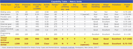
Figure 4
Energy Efficiency and Power Savings Benefits of Rotary Pumps
Energy assessments require examination of the full range of pump system application parameters, so specific study is recommended.
Rotary pumps are known for the ability to pump viscous fluids more efficiently. Figure 5 uses HI/Europump Life Cycle Cost Guideline data and compares maximum attainable rotary efficiencies to maximum attainable rotodynamic efficiencies. Specific attractiveness can be identified for applications with viscosities as low as 10 cSt (60 SSU) and differential pressures above 50-psi. It should also be noted that the chart is based on operating a centrifugal pump at its best efficiency point (BEP). If the pump is installed in a system where pressures vary, the centrifugal pump will typically move on its operating curve to a lower efficiency region.
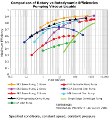
Figure 5
Having a working knowledge of rotary pump fundamentals and the specific process application and/or system for which the pump is being selected is essential for a good pumping solution. Basic differences in operating capability can be used to guide rotary pump type selection. Selecting the right pump to match the system and its operational requirements is key to reliable operation and low ownership cost.
Pumps and Systems, April 2009