


Magnetic-coupled, hermetically-sealed screw pumps solve marine booster pumps seal leakage problem.
Screw pump failure in marine fuel oil conditioning systems is one of the most frequent incidents that can affect a ship’s availability. Marine combustion engines are generally run with heavy fuel oil (HFO). This high-viscosity, residual oil requires a certain amount of pretreatment to be conditioned for use in combustion engines. Apart from the separation of water and solid sediments, the major task of the system is to reduce the viscosity so that the fuel oil can be processed by an injection pump. For this, pre-manufactured modular plants (booster modules) are used (see Figures 1 and 2). Viscosity reduction is performed by heating the HFO. The necessary extent of heating is controlled by a viscometer.
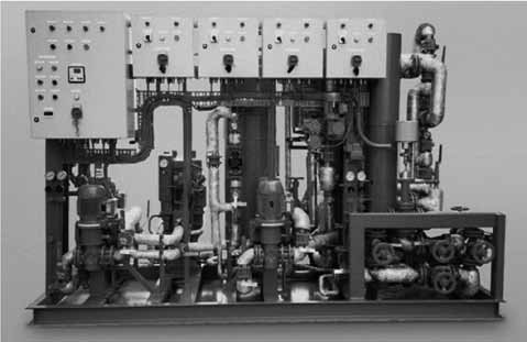 |
| Figure 1. Booster module for marine fule oil conditioning |
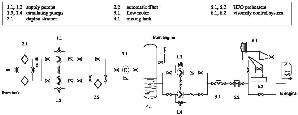 |
| Figure 2. Hydraulic scheme of a booster module |
Fuel temperatures can reach 150 C, so the fuel must be pressurized by supply pumps to avoid evaporation of residual water and low volatile components. To stabilize the control loop, the heated oil is circulated between the booster module and the engine. The rate of the circulated flow is larger than the maximum consumption of the engines. A twin set of screw pumps is commonly used for the supply unit and the circulation loop. Because a breakdown of the booster module will stop the vessel, a redundant pump is available. A defect in one pump will affect the continued operation. Recent, frequent failures prompted a detailed investigation.
Identification of Pump Failure Modes
Defects with HFO booster module screw pumps are reported as one of the most frequent failure modes affecting a ship. A systematic investigation was initiated in 2002 to examine the screw pump failures. The evaluation was based on the claims by a sample shipyard during the 1-year guarantee period. Nine vessels have been considered in this study. Because each vessel operates two supply pumps and two circulation pumps, 36 pumps were involved in this investigation.
Defects were claimed for 18 pumps, making the failure rate 50 percent. The pumps are of a mature design, used successfully in different applications for nearly 15 years. Therefore, the purpose of this study was to identify the critical conditions that contributed to such a large pump failure rate. The claimed defects were restricted to damaged couplings, destroyed bearings and mechanical shaft seal leakage. Figure 3 shows the arrangement of these elements in a typical booster pump aggregate.
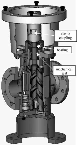 |
| Figure 3. Typical booster module screw pump aggregate |
Modes of Coupling Failures
Torsionally elastic couplings are often used (see Figure 4). A flexible geared elastomer insert separates the rigid coupling shoes. It must be emphasized that the design and the dimensions of these couplings are well-proven in a multitude of applications. The claims regarding couplings were restricted nearly exclusively to pumps operating in booster modules.
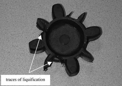 |
| Figure 4. Damaged coupling insert of a circulation pump |
A second theory explored possible dynamic overloading. The circulation pump discharges the fuel oil to the high-pressure injection pumps of the main engine. These pumps produce significant dynamic pressure peaks, which may have caused the coupling damage. After testing this theory, (see results in Figure 5), the mean pressure of approximately 10 bars, and maximum pressure peaks of not more than 11 bars, the assumption that pressure peaks caused the damages was disproved.However, the damaged couplings (some destroyed) revealed evidence of overloading. As a result, pump failure occurred because of the disengagement of the pump and motor shaft with the subsequent breakdown of the pump discharge. Repeated checking of the torque to be transmitted did not reveal any incorrect layout.
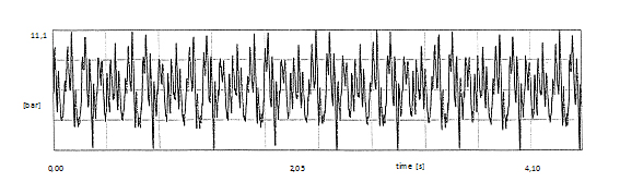 |
| Figure 5. Supply pump discharge pressure versus time |
About four months later, the same module experienced a coupling defect. The part was examined closely (see Figure 4). Because the transferred torque was unidirectional, investigators expected that only every second gear would be damaged. However, just one side was destroyed, and some areas showed traces of liquification. This suggested that overheating was the problem. Further samples showed similar conditions, indicating a unique reason for the problem. During normal operation, the temperature of the coupling was measured at about 90 C. The polymer is heat resistant up to 150 C. Only out-of-range operating conditions explained the damage.
Modes of Bearing Failures
The quality and dimensions of the bearings are also proven effective in different applications. Because of this, a lifespan of less than 2,000 to 3,000 hours of operation is unacceptable.
Figure 6 shows the poor condition of a bearing that was returned. For further information, one still-functional sample bearing was installed in a test pump. This pump was operated at an elevated suction pressure to simulate the rated bearing load. The test run also measured the temperature directly at the outer bearing ring (see results in Figure 7).
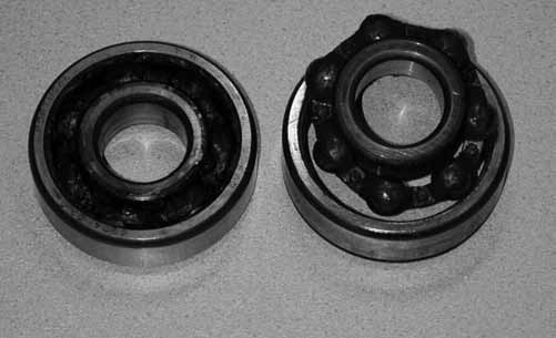 |
| Figure 6. Bearing damange after approximately 2,000 hours of operation |
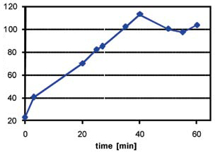 |
| Figure 7. Temperature rise [°C] in a damaged bearing |
Because of increased friction in the damaged bearing, it ran hot, up to 110 C, after about 40 minutes. At an increased temperature level—such as those found in a booster module (coupling rated temperature 90 C)—the bearing may easily produce a temperature past the plastification or even liquification temperature of the coupling elastomer. The bearing heat produced moves toward the coupling via the pump shaft, explaining why the coupling damage progressed from one side. This information connected the coupling damage to the bearing-produced heat, but what caused the deterioration of the bearings?
Modes of Mechanical Seal Failures
Mechanical shaft seal leakage accounted for a number of defects claimed during the study. In some cases, the defect manifested in heavy leakage. However, in most cases, the seal had a seeping leak not quickly detected.
In the current pump design, the leakage of the mechanical seal flowed into the motor lantern where it was drained with a pipe into the oil sump and was not detected from outside until it heavily accumulated. Apart from this, a mechanical seal requires a certain design leakage to maintain the lubrication film on the sliding surfaces. In most cases, this design leakage will not become evident because of evaporation. Low, volatile liquids or liquids that tend to form solid residues in contact with ambient oxygen may accumulate in the leakage drain.
In some instances, the motor lantern of the failed pumps was nearly completely filled with coke and carbon residues after approximately 2 years of operation. These examples revealed that early bearing damage in the booster module pumps was related to the exposure of the bearing to HFO oil leakage.
The damage to the couplings and bearings was secondary following a mechanical seal failure. The fact that nearly all claims of coupling and bearing damage accompanied a mechanical seal failure supported this. Avoiding mechanical seal failure is important for improving the performance of screw pumps in booster modules.
Permanently Deformed O-rings
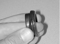
The stationary and rotating ring of a mechanical seal are commonly fitted onto the shaft, with O-rings acting as secondary seals. In most of the leaking mechanical seals, the O-rings lost their elasticity and experienced excessive permanent deformation (see Figure 8). In some cases, they showed signs of liquification as if they were melted (see Figure 9).
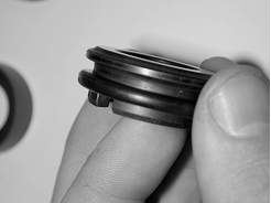 |
| Figure 8. Permanently deformed O-Ring |
 |
| Figure 9. O-ring destroyed by extreme temperature |
Wear of the Sliding Surfaces
Some of the leaking mechanical seals exhibited excessive wear on the sliding surfaces. HFO may contain abrasive solids. Because of this, the slide rings are commonly manufactured from silicon carbide, which offers wear resistance. In some cases, after only a few months of operation, the rings showed heavy traces of wear that could be the reason for increased leakage (see Figure 10).
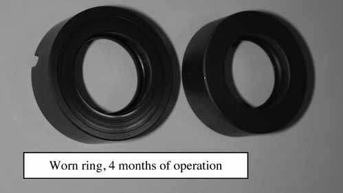 |
| Figure 10. Heavy wear on a silicon carbide slide ring. |
Solid Deposits
Another possible failure mode is the formation of solid deposits on the atmospheric side of the shaft and sliding ring (see Figure 11). The secondary seal between the rotating ring and shaft is a dynamic O-ring that has to absorb small axial displacements of the shaft. At contact with ambient oxygen, HFO tends to form solid deposits that may inhibit the axial displacement of the rotating ring. As a result, the close contact of the sliding rings will be lost, and heavy leakage will be the final result.
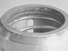 |
| Figure 11. Solid deposits may inhibit the axial displacement of the rotating ring |
Cracking of Slide Rings
In rare cases, mechanical seals also leaked because of cracks in one of the sliding rings. Silicon carbide is brittle. Under normal operation, no intolerable strokes or shocks will occur. Cracks always began from the pin slot, which acted as a twist lock. Cracks in the slide rings, therefore, were attributed to irregular operating conditions. Cold starts of the pump in high viscous fuel oil will result in drastically increased torque acting on the rings. This torque has to be transmitted by the twist lock device, and the brittle silicon carbide ring will be the first part to fail.
Improvements of Mechanical Seals for HFO Applications
Improved Elastomers for O-Rings
Fluorine rubbers (“Viton”) commonly make up the elastomers chosen for HFO handling. For many years, these materials have provided sufficient chemical resistance and temperature stability for this application. However, the results of this study have shown that a large number of pump claims have been attributed to a failure of flourine elastomer O-rings.
The acknowledged international standards on HFO (ISO, see [1]) mainly specify physical properties. The chemical composition may vary considerably. A continuous change of this composition may have contributed to an increased chemical aggressiveness. In addition, increasing oil temperatures are another factor of deteriorating influence on elastomers. As a counter measure, improved screw pumps now rely on rubbers with a higher extent of flourination. Such qualities are providing improved chemical resistance and temperature stability up to 275 C and are well-proven in the chemical industry. However, the price of these materials is higher.
Advanced Qualities of Silicon Carbide
The commissioning of a booster module is a critical phase. For instance, if the pumps are not properly filled and de-aerated, minutes may be required until the fluid reaches the mechanical seal. Beyond such dry-run conditions, slide ring temperatures will increase and reach values far above 200 C within a few minutes. O-ring damage (see Figure 9) and early leakage will be the result. Today, silicon carbide contains graphite as a solid lubricant, which will reduce the coefficient of friction in dry-run conditions(see Figure 12). The application of such materials in booster pumps, therefore, provides increased security, particularly with regard to early damage because of commissioning problems.
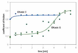 |
| Figure 12. Coefficient of friction under dry run conditions, see [2], [3]. |
Design Modifications
To avoid HFO leakage in the bearing, an advanced pump design has ensured the separation of bearing and leakage drain (see Figure 13). Leakage oil will be drained directly from the stationary sliding ring, avoiding accumulation of oil residues. The seal chamber can be modified so that a generous by-pass flow will absorb the friction heat produced at the sliding surfaces. Improved venting and flushing devices complete the design modifications for an improved shaft seal performance. The bearing cover provides enough space for an additional radial seal ring. The latter might be applied as additional bearing protection or for the application of a quench fluid to reduce the risk of solid formation.
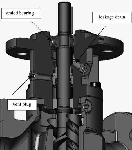 |
| Figure 13. Advanced pump design for improved shaft seal performance |
 |
| Figure 14. Magnetic power transmission of a hermetically closed screw pump |
Magnetic-Coupled Pumps
Despite the improvements, the shaft seal will always remain the critical element of a screw pump operating with HFO. Apart from the application of silicon carbide, no further option was available to decelerate the wear due to abrasive solids in the fuel. Cracks produced by cold starts in high viscous fluid also cannot be excluded. The application of a quench to control the formation of solid residues requires a notable amount of control and maintenance. Operation without quench will result in leakage problems because of inhibited displacement of the shaft O-ring.
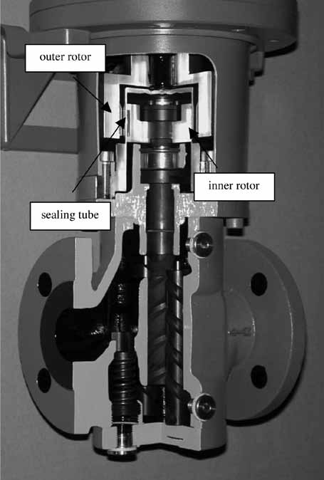
These facts show that a mechanical seal is a wearing element with restricted life expectancy. This conclusion was the reason for the development of an alternative solution for the screw pumps’ problems. The decision was to avoid a shaft seal by using a hermetically-sealed pump (see Figure 14). For this purpose, a thin-walled sealing tube covers the shaft end, forming a completely closed pump capsule (see Figure 15).
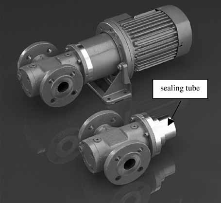 |
| Figure 15. Leakage-free hermetically closed pump unit |
The torque required for the transfer of power to the pump shaft is transmitted through the walls of the sealing tube via magnetic rotors. These rotors are equipped with a set of extremely strong permanent magnets. Advanced materials based on alloys of neodymium, iron and boron allow these pumps to reach the required rates of magnetic flux.
Hermetically closed pumps with magnetic power transmission have successfully operated in the booster modules for about five years with virtually no failures. Besides the reduced risk of contamination with HFO leakage, they offer the advantage of reduced outage time. The increased initial investment, therefore, will be balanced by reduced overhead. Considering the costs for maintenance and spare parts, magnetic-coupled pumps will end up with lower total life-cycle costs.
References:
[1] International Standard ISO 8217: Requirements for Marine Residual Fuels, 1996.
[2] Meschke, F., and Nitsche, Ch., 2001,”New SiC Materials with a Broadened Range of Performance”, ceramic forum international, Ber. Deutsche Keramische Gesellschaft, 78, No. 10, pp. E20-E22.
[3] F. Meschke, Wacker Ceramics: “Ekasic G® a special grade for tribosystems”, internal presentation, 2001.