


In a perfect world, things are always done correctly, quickly and inexpensively. In the real world, however, a compromise between cost and time is unavoidable. A new vertical turbine cooling water pump should last 15 to 25 years between repairs if the water is relatively clean and if it is operated near BEP point, with few stops and starts. Eventually, however, internals wear out and vibrations increase. To prevent catastrophic failure, the pump must be pulled and repaired.
In the January 2008 issue, we discussed the different levels of repairs, depending on the specified target of life extension, degree of damage to the internal components and cost consideration. The extent of repair depends on whether a pump needs to go back to service for another 20 years or needs to last only 3 to 5 years because the entire plant is due for shutdown or expansion. Some compromise in the repair approach can occur as long as it can be ensured that whatever solution is applied, the pump will last for at least a duration of the intended remaining planned service life after repair. Quality is not relaxed, but a meaningful balance between remaining life and cost can be found. Clearly, no compromise is to be made if safety or any other problem can be foreseen.
Consider an example of a large vertical turbine pump, 32-ft under the sole plate with two stages and a 4-in shaft (see Figure 1). It has three bronze bushing and three rubber guide bushings along the length of the column. Other materials can be used, but these are typical. Figure 1 also includes a simplified rendition of the rotor, disregarding changes of shaft diameters and not considering intermediate shafting couplings, etc. We will also assume that all bushings initially had 0.030-in diametral factory clearances (in reality, the bronze bushings would have somewhat tighter clearances, and rubber guide bushings would have somewhat larger clearances).
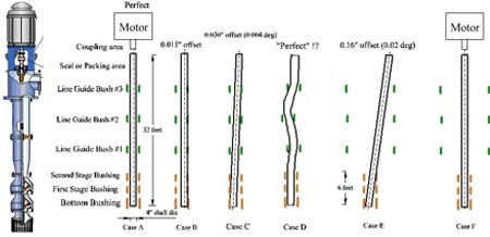
Figure 1. Rotor position depends on the clearances of the bushings as well as the concentricity of the entire unit
As shown in Figure 1, Case A, the pump shaft is perfectly lined up with the motor shaft, and is also perfectly centered within the clearance of the bushings. The maximum possible offset of the shaft, in this case, can be no more then 0.030/2 = 0.015 inches from the perfect centerline.
Before the repair process begins, the pump is dismantled, laid out and inspected. Clearances are documented, and, if excessive, all bushings are typically replaced. If bushings are worn to the point of impeller rings contacting the casing rings, then these rings are replaced as well. Sometimes, depending on the extent of the damage, even impellers need to be repaired or replaced.
Deciding on new bushing clearances seems to be easy since the clearances are listed in OEM manuals, and most repair shops are aware of these requirements based on experience. A pump repaired following these proper dimensional guidelines would essentially be at as-new condition. When the final alignment is conducted, the plant aligners would see only between 0.015-in to 0.030-in of play at the top of the shaft while centering the rotor, as shown in Figure 1, Cases B or C.
In the worst case, Case C, if the rotor seats are tilted, the first and the last bushings will determine the angular tilt and the offset. In our example, the tilt of the rotor is only 0.004-deg and results in 0.030-in offset.
However, for long vertical turbine pumps, it is not the diametral dimension (diameter) of the bushings or even clearances that is a challenge, but rather the concentricity of all bores to within each other that hold these bushings. The internal parts gradually move and distort under loads, especially for tough applications where operation off-BEP, corrosion, abrasion, etc. are present. If "perfect" clearances are applied during the repair, without checking the bore's eccentricity (which might, or likely did, distort during the 15 years in service), the shaft may become severely bent, as shown in Figure 1, Case D. The result would be severe vibrations, rub and possibly quick failure-even though the assembler aligning the pump in the field may find the shaft "perfectly centered" as it comes out of the stuffing box.
A decision may be made to actually open up the clearance of the rubber guide bushings (but not the lower bronze bushings), as shown in Case E. As shown, the three lower bearings in a 6-ft span will determine the angle of maximum misalignment (0.02-deg), with the offset reaching 0.16-in. Essentially, the clearances of the rubber bushings would not matter in determining the plumpness of the rotor as long as the alignment of the pump shaft to the motor is done correctly, as shown in Figure 1, Case F (in a highly exaggerated illustrative example).
A "perfect" alternative solution would be to remachine all fits to ensure the concentricity of the entire unit's internals is restored. That, however, is a more involved and expensive operation. If the remaining life of the equipment is not intended to reach another 15 years, it may be possible not to restore it to such perfect condition.
Clearly, such compromise should not be taken as a rule for any repair, but only be considered on a case-to-case basis. In most situations, a properly realigned rotor, even with rubber bushings clearances exceeding the as-new spec would operate fine, but rare occasions exist where this may be a problem (read the answer in the next issue).
In fact, allowing a somewhat enlarged clearance of the rubber bushing may actually be a desirable thing, as it could avoid situations as shown in Case D. The dimension of the bronze guide bushings, however, can not be compromised at all, as this would directly impact the impeller contacting casing rings if these clearances are excessive.
The lower bushings and the motor bearings ensure the plumpness of the entire rotor, especially for motors with anti-friction (ball) bearings, which can keep the motor shaft centered and the entire rotor in good vertical plump position. However, for some larger motors with journal bearings and clearances significantly larger than those for anti-friction bearings, the entire subject needs to be reevaluated. The compromises in the cases described may not be a good idea for such large motors.
Overall, if a compromise solution is adapted and accepted, it is important to clearly understand the extent and nature of such a compromise. If cost is not an issue, then a better approach to restoring concentricities of the entire unit should be followed. In that case, a stride for perfection is well justified.
As always, a parting quiz. What rare, but known, problem may exist, if the rubber bushing clearances are allowed to be excessive (Figure 1, Case F)? The first three people to answer correctly receive free tickets to our next Pump School in April.
Pumps & Systems, May 2009