


Detuning devices solve high vibration problems in power station water circulating pumps.
Mechanical resonance—the buildup of a large vibration amplitude when something is excited at its natural frequency—comes in many forms. In its most desirable state, it occurs in music. Instruments and acoustics are finely tuned to produce dramatic and beautiful resonant effects. In its most undesirable state, mechanical resonance has extremely dramatic effects.They can cause bridges, structures and machinery to break or malfunction, resulting in dangerous and expensive failures.
Engineers work diligently to fine-tune mechanical structures and machinery to reduce or eliminate the effects of mechanical resonance before construction or installation. Engineers must account for the following factors when designing pumping systems to avoid mechanical resonance:
- Operating speed
- Foundation stiffness characteristics
- Drive reed critical frequency
- Bearing span
- Bearing damping coefficients
- Bearing stiffness coefficients
- Drive mass and distribution
- Pump mass and distribution
- Pump fluid
- Geometry of the rotor and structural components
When assumptions are wrong or the actual installation does not mirror the engineering models, the potential for mechanical resonance could exist if the system’s actual natural frequency is too close to the operating speed. Issues do arise, often from unexpected foundation conditions or inaccurate drive reed critical frequency data.
Natural Frequency in Pumps
A mechanical system’s natural frequency is a function of its weight and stiffness, most commonly expressed as:
ωn = √(k/m)
Where:
ωn = natural frequency
k = stiffness
m = mass
For horizontal pumping systems, the solution to resonance issues has generally involved simple modifications that increase system weight, reducing natural frequency as a result and creating an adequate margin from the operating speed.
Resonance issues can be much more difficult to address with large vertical circulating water pumps. Typically found in power generation, steel manufacturing, water intake and flood control applications, these massive, expensive pump installations can be difficult and costly to modify once installed. Because of these difficulties, engineers are forced to employ more sophisticated techniques that alter system stiffness as a means of changing natural frequency once pumps are installed.
Often, this can be accomplished by adding frequency detuning devices to the pump system structure. In principle, the addition of these devices reduces system stiffness, lowering its natural frequency away from potential points of excitation. While this practice has been around for decades, advances in testing and modeling techniques have made design and application of detuning devices extremely reliable, avoiding the unnecessary and costly trial and error previously associated with this technique.
Frequency Detuners for Vertical Pumps
Axial and mixed-flow vertical circulating water pumps (see Figure 1) are wet-pit installations with these main components:
- Suction bell
- Rotor assembly (impeller, shaft, bearings, couplings and drive rotor)
- Column
- Discharge head
- Drive (not shown)
In this type installation, one of the easiest and most inexpensive places to affect a change in natural frequency is at the interface between the discharge head and the driver. A detuning device for this type pump system consists of two carbon steel plates (sometimes called spring plates) mounted between the driver flange and the pump driver support flange of the discharge head. A gap between the cantilevered portions of these plates adds flexibility to the system—like a pair of springs acting in series—reducing system stiffness. To illustrate the engineering and application of detuning devices, consider the following circulating water pump application at a Midwest U.S. power station.
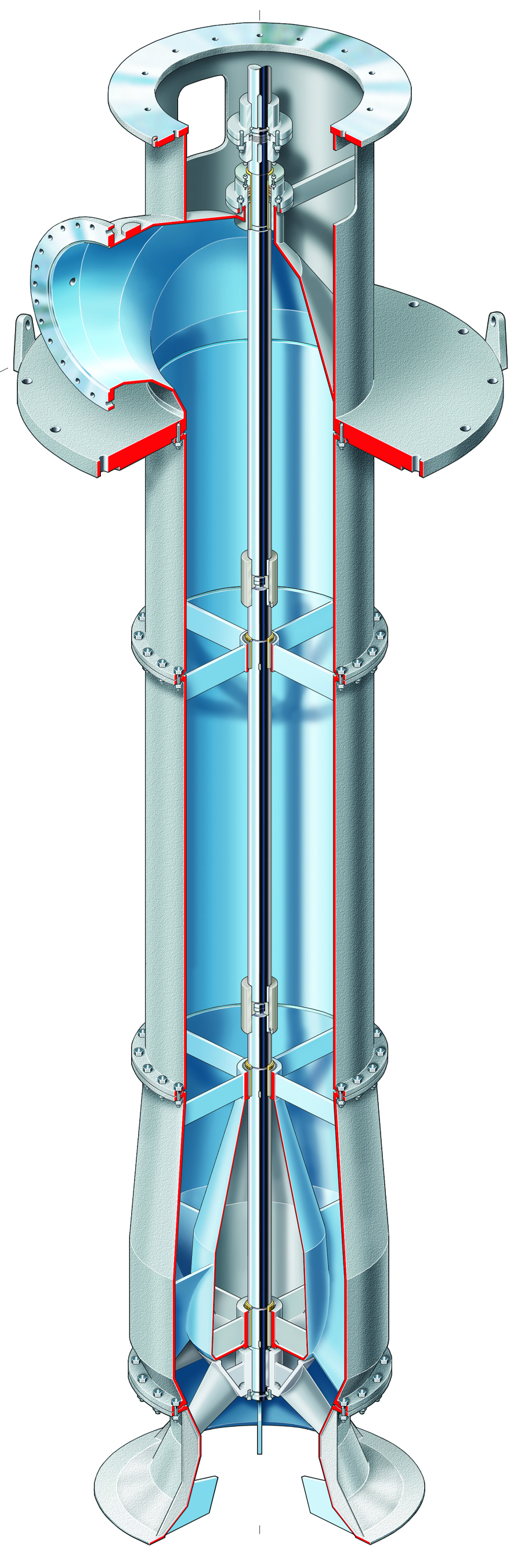
Figure 1. Typical vertical circulation pump
Frequency Detuning in Practice
Despite careful engineering, two vertical circulating water pumps exhibited higher than expected vibration levels shortly after installation (see Figure 2). Engineers performed thorough vibration analysis on both units, revealing high amplitudes in both systems, the most severe being in Unit 1B. Measurements for Unit 1B are shown in Table 1. To identify and confirm a resonance issue, consulting engineers engaged in the following field testing and analysis.

Figure 2. Original pump installation at the power generation plant
Impact Testing with a Calibrated Hammer
In this method, engineers strike the pump system at multiple locations using an instrumented hammer and use a vibration sensor and a vibration analyzer for measurement. This method of striking a system with a mass and measuring its response is common for determining natural frequencies in mechanical structures. Best practice requires that the impact testing take place at multiple locations on the structure to identify several resonant frequencies. This test must be performed with the pumping equipment off. The recorded first and second natural frequencies are shown in Table 2.
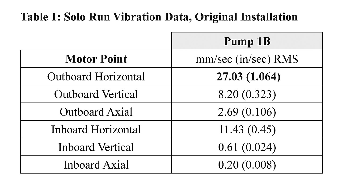
Table 1. Solo run vibration data, original installation
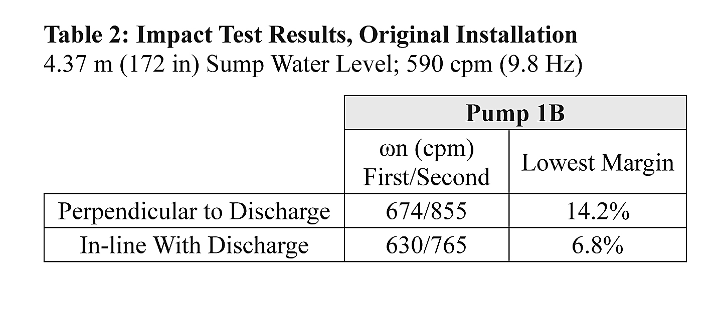
Table 2. Impact test results, original installation
Peak-Hold Coast down Test
To confirm the resonant frequency issue, engineers performed a second test known as a peak-hold coast down test. In this test, the driver is decoupled from the pump, started and allowed to coast down from its normal rotational speed. Engineers record the maximum vibration amplitude at each spectral line during coast down, noting rises in amplitude. The speeds at which the amplitudes increase can indicate a natural frequency. In this case, the maximum amplitude occurred at 600 cycles per minute (cpm), which varied from published reed critical frequency data. This testing confirmed the impact test results (see Figure 3).
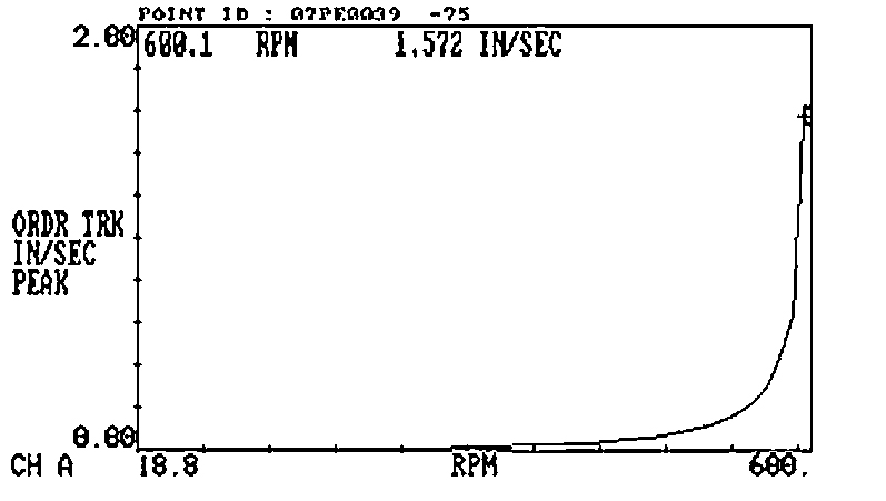
Figure 3. Motor peak-hold coast down test, original installation
Applying Detuning Devices
Taking into account the acquired data, the assumption was made that the high vibration levels were the result of mechanical resonance, as indicated by the low margins between the required operating speed (590 rpm) and the measured natural frequencies. Accordingly, the application of detuning devices to reduce system stiffness and, subsequently, natural frequency was determined to be an effective course of action.
Using advanced mechanical and stiffness analysis techniques, consulting engineers determined the appropriate size, thickness and gap widths for the plate assemblies. An engineering model of the modified system was developed to confirm the maximum deflection levels to assure that the cantilevered portions of the mating plates would not touch under any condition. Finite element analysis (FEA) was performed to confirm system parameters—the predicted system natural frequencies and mode shapes at operating conditions. This analysis considered:
- The base geometry of the motor support, discharge head, bowl and suction bell
- The mass of the fluid in the pump, sump and discharge head
- An equivalent model of the driver (by mass and center of gravity), including reed frequency
- The sump geometry and mass, including concrete properties
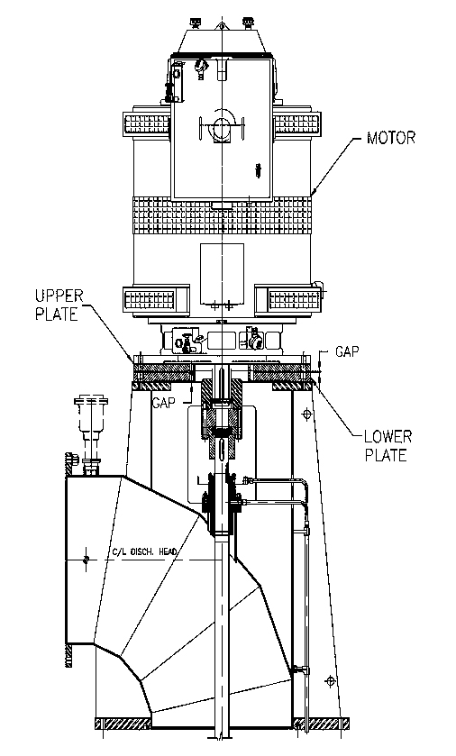
Figure 4. Arrangement drawing for detuning devices
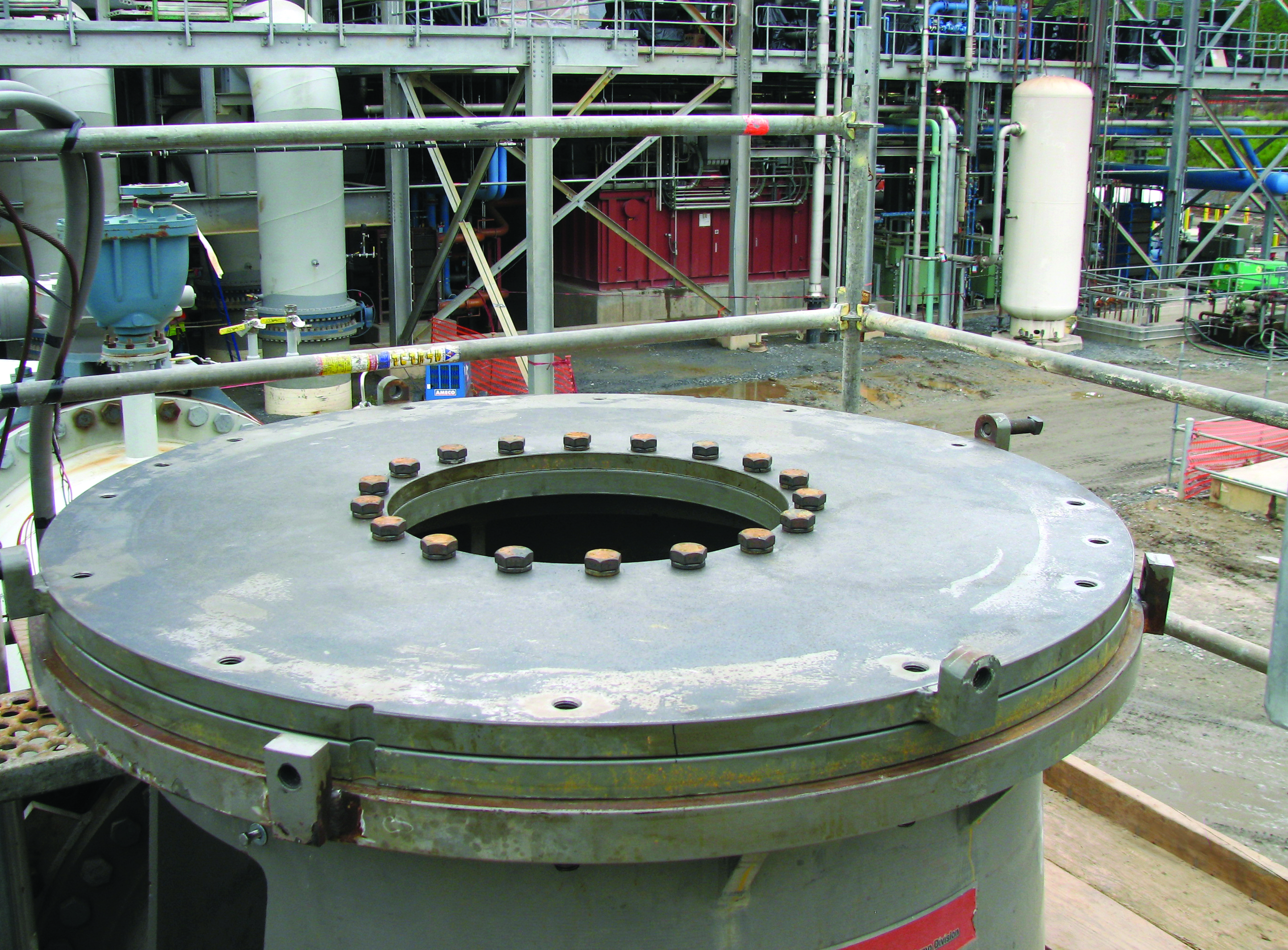
Figure 5. Installed detuning devices
Figures 4 and 5 show the detuning devices in the pump assembly. Once installed, engineers repeated the impact and peak-hold coast down tests to validate that the natural frequencies of each pump system had been sufficiently reduced to eliminate resonance issues. Field test results for Pump 1B are shown in Table 3 and Figure 6. Testing showed that the margin between the system’s natural frequency and operating speed was increased to a comfortable 35 to 40 percent, significantly better than the accepted minimum standard of +/-25 percent.
Of course, confirming reductions in actual vibration levels once the system was operating again was the most important measure of success. A thorough analysis was performed under normal operating conditions, and the results confirmed the efficacy of the detuning plates, with all vibration measurements well within established acceptance criteria (see Table 4).
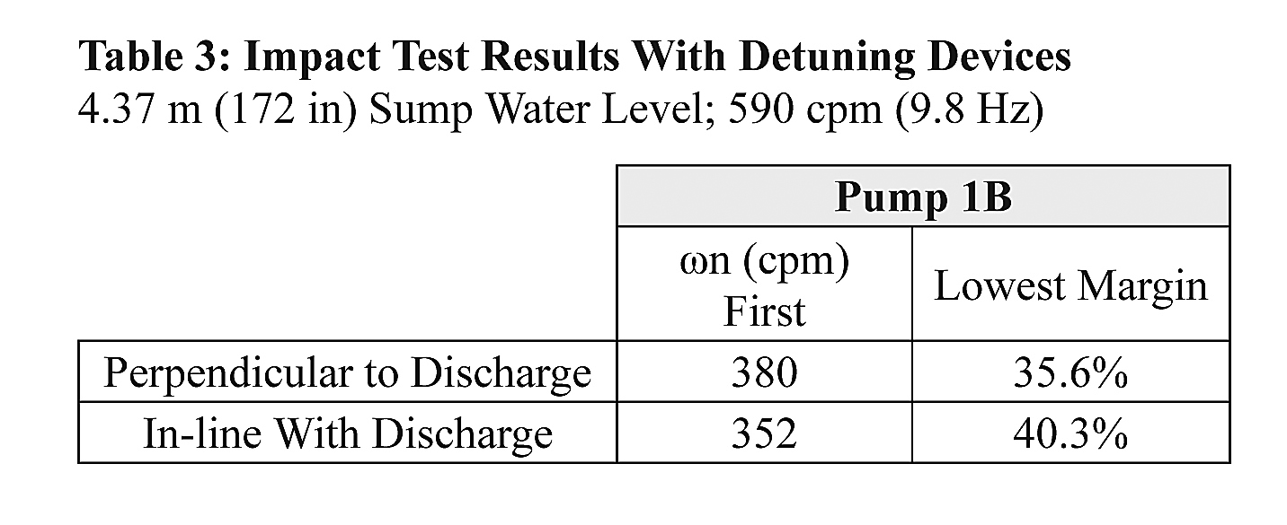
Table 3. Impact test results with detuning devices
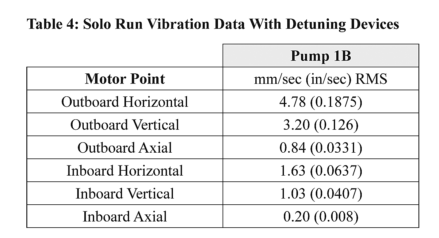
Table 4. Solo run vibration data with detuning devices
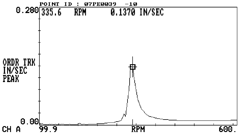
Figure 6. Motor peak-hold coast down test with detuning devices
A Predictable, Reliable Solution to Mechanical Resonance
While the practice of frequency detuning has been understood for decades, advances in diagnostic techniques, engineering models and mechanical analysis have made the design and application of detuning plates extremely predictable. This is important for large, critical, continuous-duty installations in which modifications must be made quickly, inexpensively and with minimal disruption to plant operations. The application of frequency detuning devices has been known to bring harmonious resonance to the ears of plant operators—in the form of low vibration and worry-free vertical pump operation.
Pumps & Systems, May 2012