


With its 40,000-kW (53,640-hp) drive rating, the CHTA 140/5 feed pump in the Niederaussem lignite-fired power station near Cologne is one of the two largest feed pumps ever built.
The new power station is situated in the immediate vicinity of the open-cast lignite mining sites in the Cologne/Aachen area. Its power output of 1,000-MW and net efficiency of 43 percent make it the world's most modern and efficient power station. This excellent performance comes from all the components of the power station unit being perfectly matched to the process as a whole.
The CHTA is a so-called “hundred percent pump,” meaning it is not backed up by a stand-by pump. Plant outages are every power station operator’s nightmare because of the immense costs involved. This pump, therefore, has to be hard-wearing, insensitive to extreme duty conditions, and provide reliable service for long periods without maintenance.
That’s not all. Energy supply companies expect very high efficiency because every kW not consumed by the pump – which operates around the clock – can be sold to their clients.
Turbine Drives Pump
The pump is driven by its own steam turbine with continuously variable speed control. The turbine has a power rating 44-MW and is equipped with two shaft ends (see Figure 1). One shaft end is directly coupled to the CHTA pump.
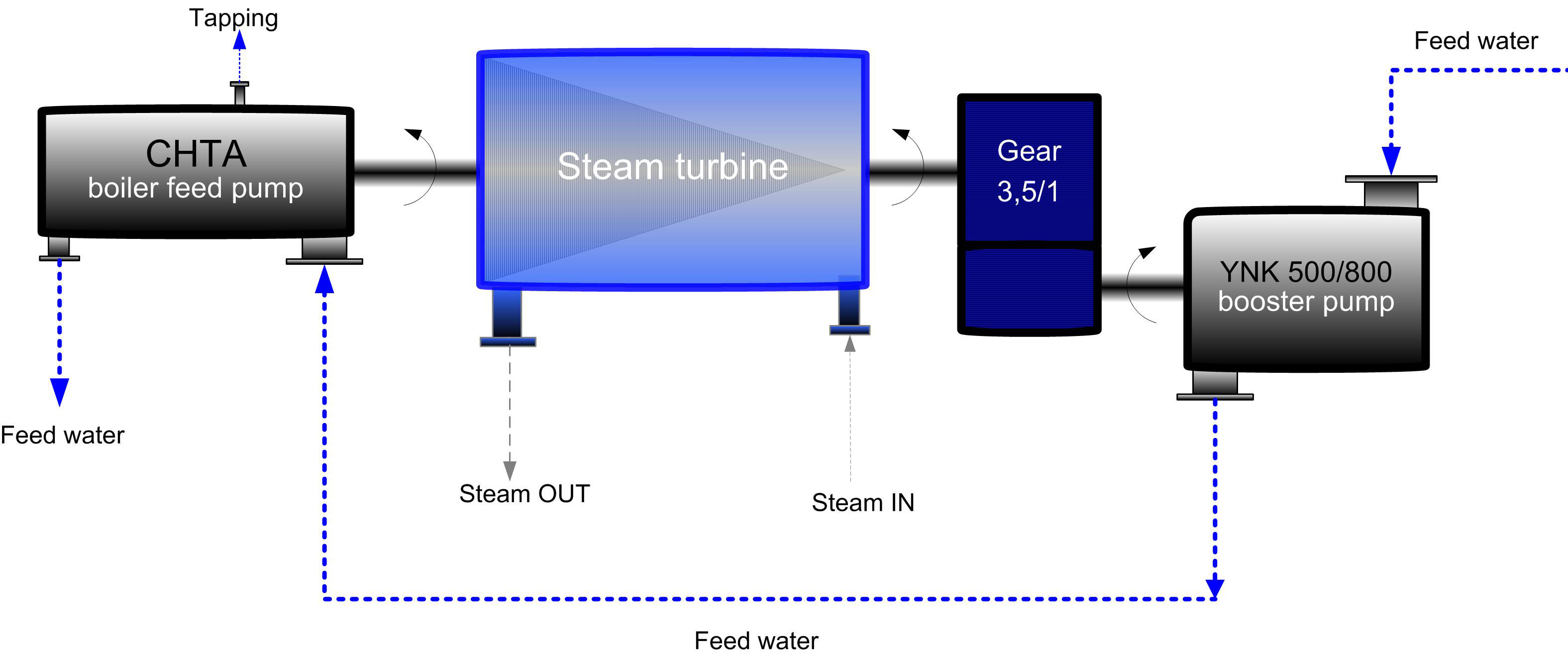
Figure 1. Simplified schematic of the steam turbine and the two pumps.
The other, on the opposite side of the turbine, drives a YNK 500/800 booster pump which supplies the main pump with the necessary inlet pressure (see Figure 2). The booster is not coupled to the turbine directly but to a gear which reduces the speed at a ratio of 3.5 to 1. Running up and low flow operations are normally taken care of by two electric motor-driven start-up pumps, each with an output of approximately 35 percent of that of the CHTA.
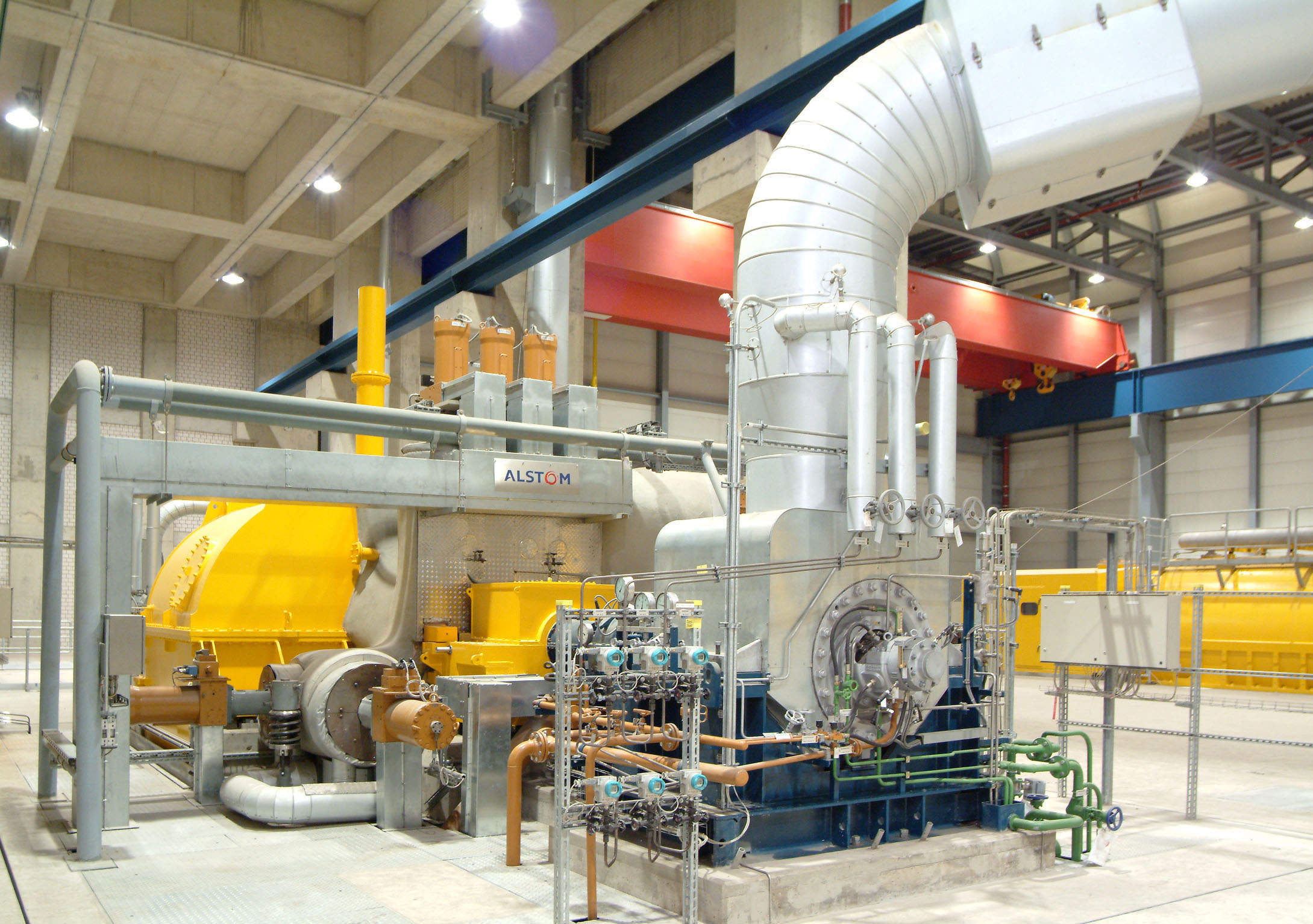
Figure 2. A YNK 500/800 booster pump supplies the main pump with the necessary inlet pressure.
During these phases of operation, the main boiler produces too little steam to operate the turbine. In exceptional circumstances, the steam needed to start up the pump and run up the unit while the pump is still cold can also be supplied from an auxiliary boiler.
Special Vane Profile Required
As the pressure in the system can change enormously in response to the operating conditions of the power station unit, the first stage impeller is the most sensitive part in every boiler feed pump. The plant operator’s specification called for a minimum of 50,000 hours of operation without cavitation-induced wear. Cavitation is the term generally used to describe the formation and subsequent implosion of cavities in a fluid.
To meet this requirement, a special vane profile was designed for the suction stage impeller, using numerical flow modeling that allowed the pump to be operated without cavitation across the entire relevant operating range and with a sufficient safety margin from the system’s NPSHA, the energy provided by the system immediately upstream of the pump.
To meet the taxing demands on the pump set, a number of special components were designed. For example, the floating ring seal was incorporated into the pump design. It is very reliable, even at peak running speeds of 50-m/s (164-ft/s) and more, which are common on high specific speed pumps. Other exceptional features of this seal are its thermal characteristics and the way these positively affect the pump’s operation. We will come back to this aspect later.
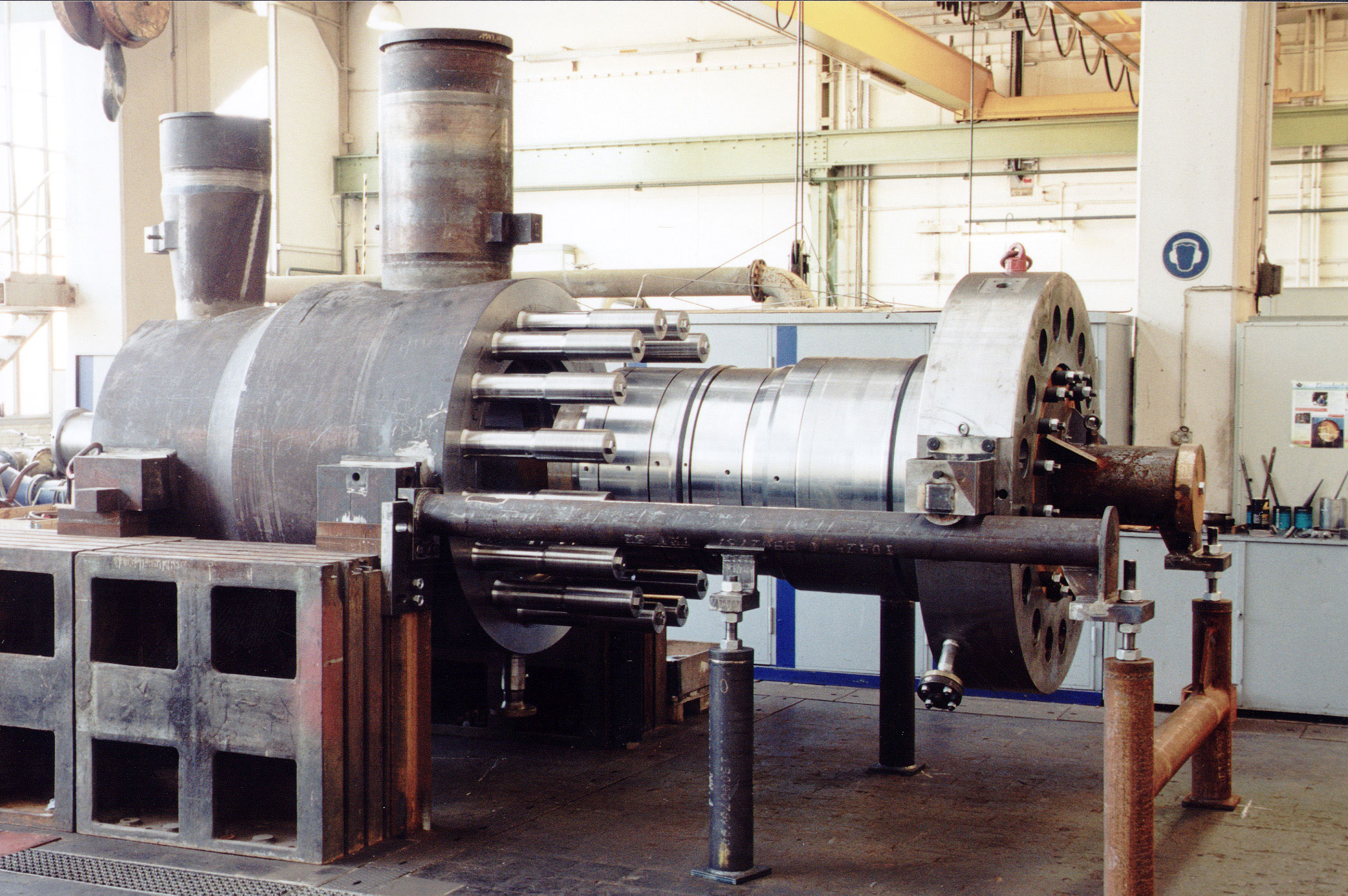
Figure 3. Assembly of the CHTA 140/5 for Niederaussem.
Hydraulic design
At the 100 percent duty point, when the power station operates at 100 percent rated load, the main feed pump has the following performance data:
Flow rate &mring; = 698 kg/s
(Q = 2,898 m³/h (12,760-gpm))
Head H = 3,361 m (11,024-ft)
Pressure increase Δp = 285.7 bar (H = 3,361-m (11,024-ft))
Speed n = 4,620 rpm
Power P = 26.47 MW (35,500 hp)
Efficiency η = 86.9 percent
Weight 40 Tons
At the so-called TÜV point, the point at which the safety valves are activated, the pump set reaches a maximum speed of n = 5,217-rpm. It delivers hot water at a rate of 893-kg/s and has a power input of just under 42-MW (around 2-MW of which are required for the booster).
The total head is divided among five stages, with a tapping (or withdrawl of a partial flow at lower pressure) downstream of the first stage. The hydraulic designs of the impeller and the individual stages give us a specific speed of:
nq = n · √Q ÷Hst0.75 = 31.4
(1,622 in US units)
Where n is expressed in [min-1], H in [m], and Q in [m³/s].
The Suction-Stage Impeller
The most critical pump element in terms of fluid dynamics is the so-called suction, or first stage, impeller. The specification stipulated a guaranteed minimum period of operation of 50,000 hours without cavitation-induced wear, which is a major concern for operating turbo machinery. Cavitation is expressed by the so-called NPSH value and is governed by the following relationship:
!
NPSHA (system) ≥ NPSHR (pump)
The NPSHA here is expressed in meters and already takes into account the pumped fluid's vapor pressure. This is why it is commonly referred to as Net Positive Suction Head, which must not be confused with the NPSHR value of the pump (the energy required at the pump's inlet to avoid cavitation altogether or at least prevent it from damaging the pump internals). The NPSH "required" by a pump depends on the properties of the impeller material and on the velocity of the flow in the impeller inlet area. The latter results from the circomferential speed u11a at the outer impeller inlet diameter and is a linear function of the speed of rotation (see Figure 4).
u11a = ∏−D11a −n
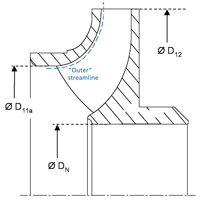
Figure 4. Suction stage impeller (schematic).
It has a major influence on the so-called material loss rate VA, which indicates the erosion phenomena caused by cavitation. Previous experience shows that the material loss rate becomes extremely high at circumferential speeds (u11a) of more than 70-m/s (230-ft/s).
Under these conditions, even impellers made of high-grade materials will soon begin to show signs of damage if subject to the slightest cavitation. In order to guarantee the lifetime specified, the pump must be able to operate at the main duty points (points on the characteristic curve where the pump is mostly operated) without any risk of cavitation:
NPSHA > NPSHR = NPSHi
Where NPSHi is incipient cavitation.
Consequently, the main criterion for designing the suction stage impeller is to develop a geometry that ensures non-cavitating pump operation.
Simulating Flow in the Impeller
At the blueprint stage, the design properties were demonstrated by numerical flow analysis. The findings were then verified experimentally by cavitation testing.
The design tool used for this is an accurate method of numerical flow modeling, based upon 3D Euler equations, that simulates the flow patterns inside the impeller to provide information on the local pressures and velocities occurring at any point of the impeller channel. This method provides a very good compromise between speed and reliability. Figure 5 shows an example of this kind of analysis.
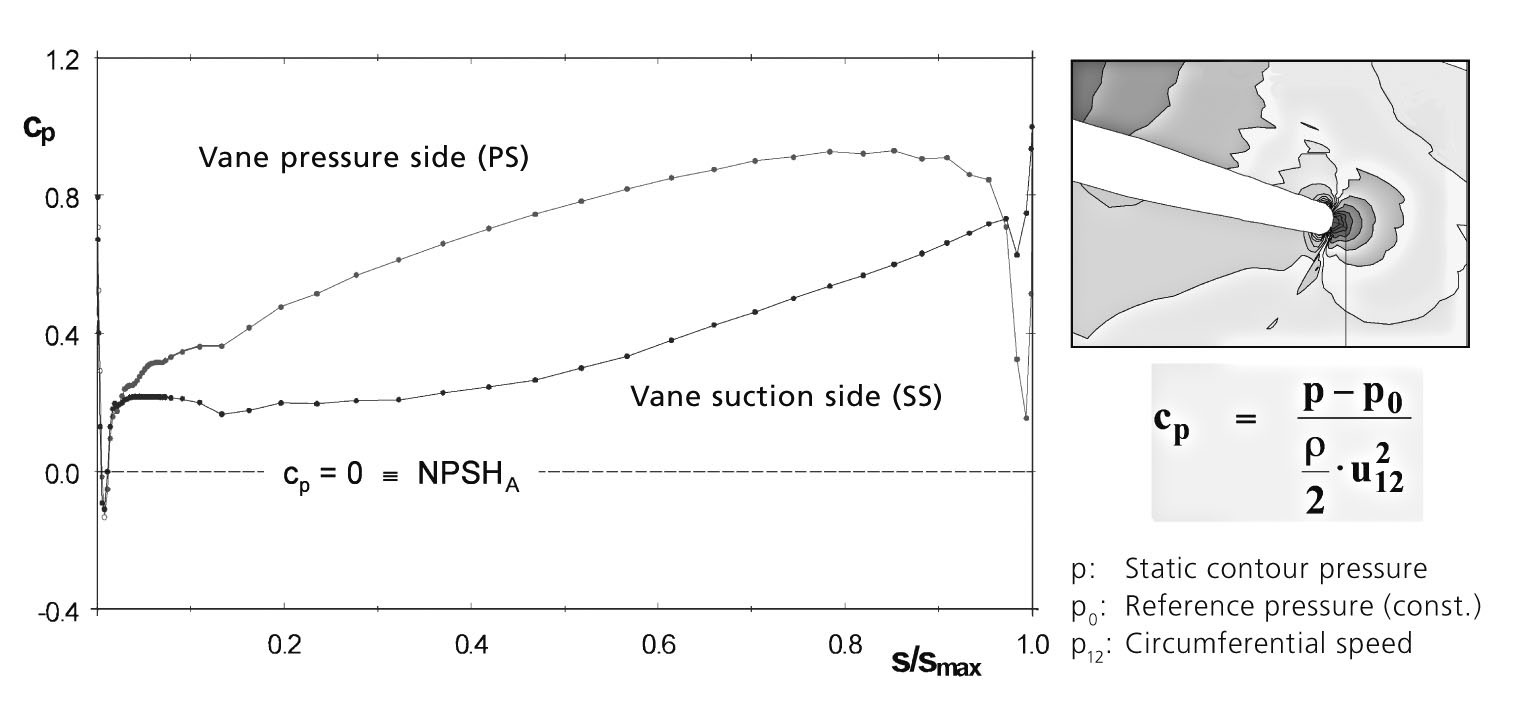
Figure 5. Computed pressure distribution (example).
After a series of optimization runs has produced the final contour, the ideal geometry must be translated into the actual component with the highest possible degree of accuracy. To do this, the inlet areas of oversize vane blanks are reduced to their final dimensions by electric discharge machining, a precision metalcutting technique.
Cavitation Testing
To verify that the suction stage impeller actually gives non-cavitating operation at the critical duty points, the impeller was installed and tested as a single-stage pump on a cavitation test bench specially built for this purpose.
The test arrangement was fitted with a replica of the original suction elbow, which featured a Plexiglas window that allowed viewing of the flow behavior and bubble visualization test.. The observed NPSHi (the NPSH value at which cavitation starts to develop) values had a sufficient safety margin from the NPSHA values, and agreed very well with the computed values (see Figure 6).
The plotted NPSHA values resulted mainly from the head of the booster pump (converted to the conditions of the test arrangement), whose main task is to increase the suction pressure to the level required by the high-speed main pump immediately upstream of the suction impeller.
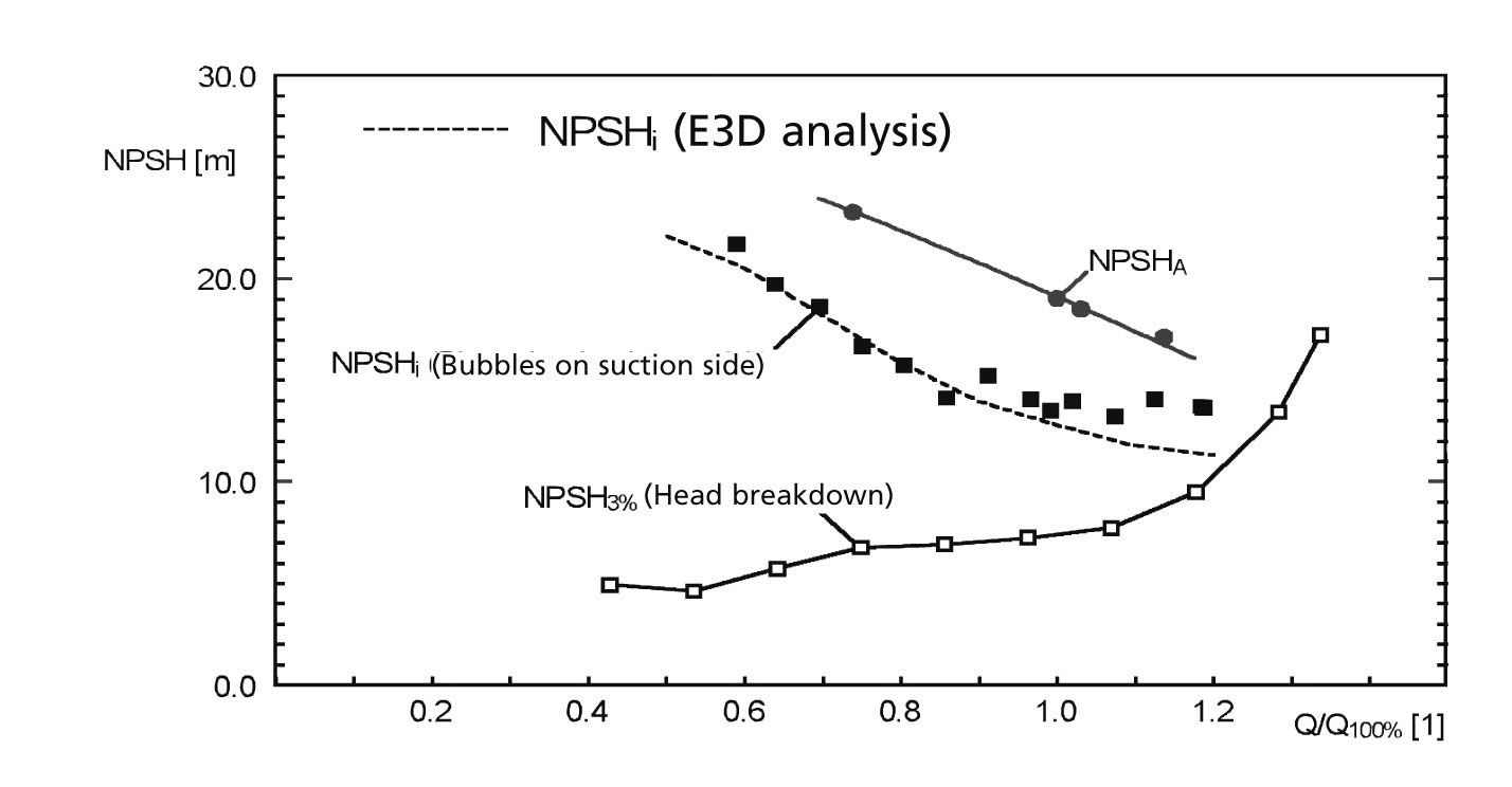
Figure 6. Results of a “bubble visualization test.”
The Rotor
The main purpose of the rotor is to transmit the power transmitted by the drie turbine to the pump shaft to the impellers. THese are mounted on the shaft by way of a rigid and wear-resistant connection (see Figure 7, part 1).
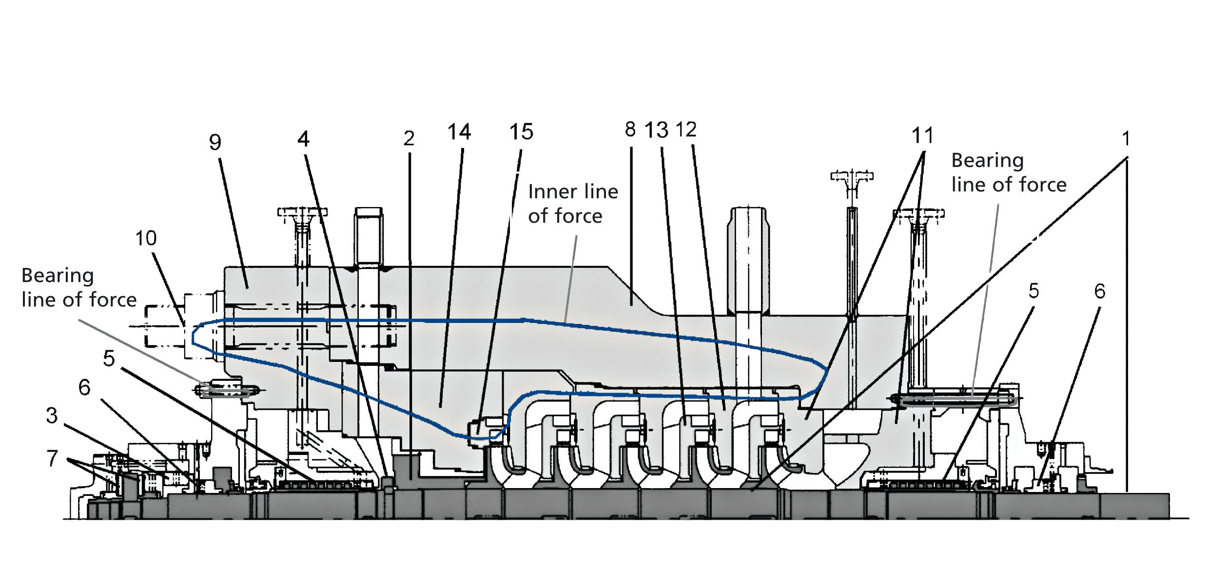
Figure 7. Main lines of force acting on the stationary components.
The pressure distribution around the impeller gives rise to a hydraulic axial thrust (see Figure 8) which is transmitted to the shaft by means of a separate split ring for every impeller.
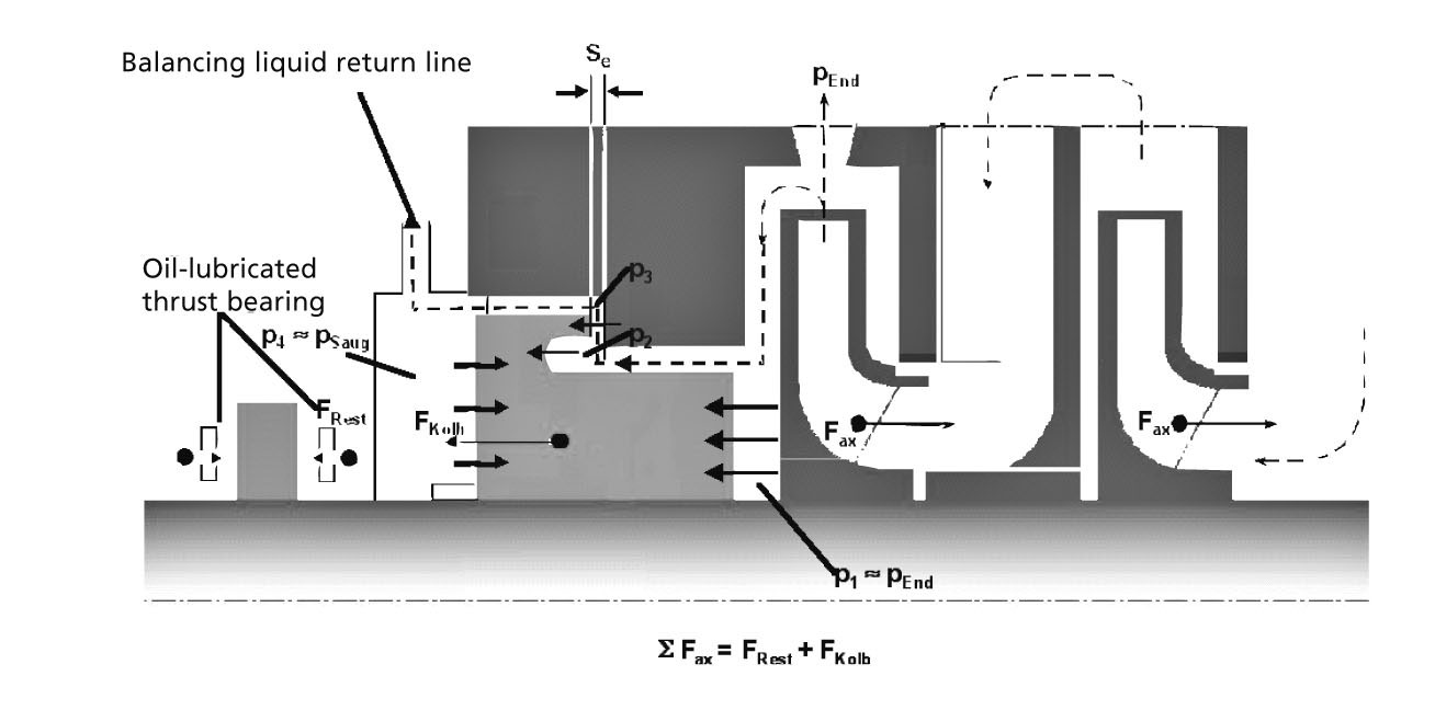
Figure 8. Axial thrust balancing.
The axial thrust, which increases in intensity from one impeller to the next and can eventually reach a maximum value of 240 tons, is reliably balanced by a doubled drum (see Figure 7, part 2). Thanks to its hydraulic properties, the double drum permanently reduces the forces acting on the thrust bearing and thereby protects it against overloading, even in the event of sudden transient load changes.
The Shaft Bearings
Grooved multi-lobe plain bearings were selected as radial bearings based on the previous positive experience with this type of bearing in terms of load-carrying capacity and dynamic properties (see Figure 7, part 6). Like the thrust bearing, the plain bearings are lubricated with pressurized oil supplied from the turbine's oil supply system.
The tilting-pad thrust bearing for load in either axial direction (see Figure 7, part 7) is reliably protected against a sudden reverse of the residual axial thrust (the residual axial thrust in the thrust bearing acting in the opposite direction). Together with the balancing properties of the double drum, the bearing effectively protects the pump against overloading and the harmful effects of sudden load transients, or changes over time in the pump’s load condition under operation.
The Stationary Components
The most striking feature about the CHTA 140/5 on first sight is probably the pressure boundary. It consists of a forged barrel casing (see Figure 7, part 8) and a cover (see Figure 7, part 9) which – securely located by the main tie bolts (see Figure 7, part 10) – is designed to retain the internal pump pressure.
The tie bolts are tightened with a hydraulic tensioning tool. This allows the bolts to be tightened unaffected by torsion or flexion moments. These bolts withstand higher loads than any others in the entire pump and must be designed with the required reliability.
Taking On Maximum Load
The pressure forces generating the axial thrust on the rotor also have an effect on the stationary parts. For the main tie bolts that secure the cover against the internal pressure, this means they must withstand a maximum load of 3760 tons!
A spring element, the compensator, provides a sufficient level of preloading of the internal components to keep them locked in place even during a phase of low internal pressure. It also compensates the different degrees of longitudinal expansion of the pump internals and barrel as a result of the uneven temperature distribution typically occurring during transient load changes.
In a hot shock situation, where the cold pump is suddenly traversed by hot feed water at a temperature of 392-deg F (or 200-deg C), these differences can measure several millimeters in length, and have to be balanced without affecting the installation’s availability or causing damage. As the pump gains speed, the internal pressure increases the rigidity of the pump components. The lines of action of the internal forces are crucial for the vibration characteristics of the pump running at full load.
In the low-excitation hydraulic system, a hydraulic concept that ensures that the (design-inherent) interaction between the rotating impeller and stationary diffuser produces only minor vibration excitation, or none at all, an undivided line of action of the internal forces is of major importance (see Figure 7). If the bearing forces can be separated from the hydraulic forces upon entering the barrel, the pump’s operating behavior will benefit greatly.
One advantage of the low vibration level was that the pump produced such little noise that the planned sound-absorbing cover was unnecessary. The static seal elements required to seal off the pressure to atmosphere are designed as profile rings capable of sealing off 500-bar (7,250-psi) pressure maximum. Their sealing action links directly to the surrounding system pressure, causing the sealing lips to be pressed against the components to be sealed off. No other forces are needed to achieve the sealing effect. A further advantage of this seal type is that it does not reduce the joint pressure other parts need for their sealing function, such as the metal-to-metal sealing of the stage casings.
The Shaft Seal
In recent years, many power station owners and operators have learned the hard way that, of all the parts of a feed pump, shafts seals are particularly highly sensitive components. They can make or break the availability of an entire power station. Since floating ring seals have provided many years of reliable service in the older units of the Niederaussem power station, this seal type was also selected for the turbine-driven CHTA in the new Unit K.
In the seal, the pressure is relieved from suction pressure to atmospheric pressure along a multi-stage throttling distance made up of “floating rings.” Depending on the pump’s duty point, the pressure drop can be as high as Δp = 40-bar (580-psi). As the pumped fluid flows through the annular gap between shaft and floating ring, it assumes a carrying quality which causes the ring to float (non-contacting principle).
To stop the flow of hot water from the pump into the seal from evaporating in the process, and to prevent the throttling rings from losing their carrying function as a consequence, the system must be sealed off with cold water. The cold water is injected at the end of the first throttling section. The injection rate is controlled by a regulating valve positioned at the inlet. As the cold condensate mixes with the hot feed water from the pump, the heating rate of the total flow of leakage can be measured and the measured value taken as a parameter for controlling the valve. The leakage flows into a tank with level monitoring and feeds from there into the condensate system.
Two (2) 100 percent pumps (one duty, one stand-by) make up the seal condensate supply system. Therefore, the supply of condensate to teh seals is guranteed. A simplified schematic of the barrier condensate circulation of the floating ring seal is shown in Figure 9.
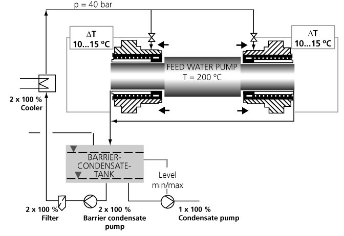
Figure 9. Barrier condensate cycle of the floating ring seal.
Planned Maintenance Intervals
Whenever the CHTA pump shaft is turning, including when it is used in turning gear mode, the barrier condensate system must be operating as well, because that is the only way to stop the rings from coming into contact with the rotating shaft. After all, with planned maintenance intervals between three and five years, the shaft seal system must be absolutely dependable.
Turning Gear Mode
Any standstill of a hot water pump of this size results in temperature stratifications of the fluid pumped. With tolerances being this close, the temperature differences will cause jamming of the shaft and floating ring seals. The drive turbine is, therefore, equipped with an electric motor to keep the pump moving at approximately 100-rpm.
During the commissioning phase of the feed pump, the thermal characteristics of this shaft seal type proved particularly valuable. As there is always a fluid flow in axial direction through the section of the shaft where the floating ring seal is located, hardly any thermal stratification develops in this area. A system equipped with a mechanical seal would respond differently. It would require jacket and circulation cooling, and the cold medium t ≈ 140-deg F (t ≈ 60-deg C) used by both cooling systems would continually create new temperature stratifications on being mixed with the hot feed water t ≈ 392-deg F (t ≈ 200°C).
Temperature differences of this kind develop above all when the pump is run in turning gear mode and may cause shaft deflection and/or deformation of the pump casing. The joint action of these effects can lead to such severe distortion that the rotor may run against the casing in less than a minute. Typical consequences are overloading and failure of the turning gear. When this happens, the pump must be cooled down to a much lower temperature so the deformation is reduced and the rotor can turn without touching the casing. These processes are absolutely crucial for the availability of a feed pump.
Remote Monitoring
At the operator's request, the pump unit is monitored by a complex telemonitoring system comprising some 50 sensors that directly transmit the measured data to the Frankenthal-based pump and service specialists. This provides the basis for condition-based maintenance and early detection of potential problems.
A “Well-Tempered” Pump
An event during the commissioning phase demonstrated the excellent thermal characteristics of this truly “well-tempered” pump. Due to a fault in the turbine's control logic, the pump – filled with hot feed water of 356-deg F (180-deg C) – did not run for all of 31 minutes. After that, the automatic control system inadmissibly returned it to service in turning gear mode. And the rotor started turning again smoothly! An incident of this kind would normally cause the pump to break down.
Summary
With its 40-MW drive rating, the Niederaussem feed pump is one of the most demanding developments realized in the past couple of decades. Specially designed vane profiling guarantees non-cavitating operation of the suction stage impeller, which was proven by a series of theoretical and experimental evidence. The system pressure, the temperatures involved and its high speed of rotation subject the pump set to extreme mechanical and thermal stresses.
Along with the bearing arrangement and the method of axial thrust balancing, the real technological highlight of this pump is the shaft seal, a sophisticated floating ring seal. The results of intensive in-house testing and the wealth of data obtained during the commissioning phase at the power station provided ample proof that the CHTA 140/5 meets all of the technical and economic requirements originally specified.
Pumps & Systems, December 2006