


Q. I know that water hammer can do substantial damage to pumps and piping. What can be done to remove this threat?
A. The following comments are taken from an HI Standard, ANSI/HI 2.3 Vertical Pumps for Design and Application:
Water hammer is an increase in pressure due to rapid changes in the velocity of a liquid flowing through a pipeline. This dynamic pressure change is the result of the transformation of the kinetic energy of the moving mass of liquid into pressure energy.
When the velocity is changed by closing a valve, starting or stopping a pump, or by some other means, the magnitude of the pressure produced is frequently much greater than the static pressure on the line, and may cause rupture or damage to the pump, piping, or fittings. This applies to both horizontal and vertical pump installations.
The head due to water hammer in excess of normal static head is a function of the rate of change of velocity, the size and length of the pipe, and the velocity of pressure wave along the pipe. The value of water hammer can be calculated with a fair degree of accuracy, provided all of the factors influencing water hammer are known.
Water hammer may be controlled by regulating valve closure time, reducing pump acceleration or deceleration, or by application of relief valves, surge chambers and other means. However, vertical pumps whose length from discharge centerline to sump liquid level is greater than atmospheric pressure, typically 34-ft, will always produce a vapor or air pocket in the column that upon restart will usually result in water hammer. This will happen regardless of whether the discharge valve is a slow-opening gate valve or a check valve.
The installation of an air-vacuum release valve may be necessary when a vertical pump will have to drive air out of the column when starting. When the pump stops, the air-vacuum release valve allows the water in the column to flow backward through the pump. If the pump discharge is open to the atmosphere, an air-vacuum release valve is not necessary.
Q. I have seen vertical turbine pumps that are built with vertical hollow shaft motors and others with vertical solid shaft motors. What factors would lead to one design or the other?
A. Vertical hollow shaft motors are more commonly used on deep well pump applications. They are built with angular contact or tapered roller bearings that can support the high down thrust from impellers without a back wearing ring generating high down thrust.
This bearing design has little or no provision for supporting upward thrust from impellers, which often occurs during start up. At that time the discharge pressure has not built up, and there is a high rate of flow causing up thrust due to the momentum change as the flow changes from axial to radial in the impellers. To protect against up thrust, the motor includes a coupling at the top which disengages and prevents motor damage. See Figure 2.4a.
If the motor reverses due to electrical phase reversal or other faulty condition, and the pump shaft joints start to unscrew, the coupling will disengage before major damage is done.
The top section of the pump shaft, which extends through the hollow shaft of the motor, has a threaded section at the end which engages an adjusting nut for setting the proper axial position of the pump rotor for proper operation. With pumps as long as 600-ft in length, the length of threaded shaft could be many inches.
Finally, such motors may be built with a non-reverse ratchet which prevents the pump from running in reverse when the pump is shut down.
The solid shaft motor is more commonly used with short setting pumps up to 20-ft or 30-ft long. It usually does not have the down thrust capability of the hollow shaft motor. Axial adjustment of the pump rotor position is made with an axially adjustable rigid shaft coupling. This coupling also provides more direct support to the shaft in the stuffing box or seal area which improves mechanical seal operation. See Figure 2.8.
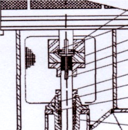
Figure 2.8—Solid shaft motor
Q. Mechanical seal failure represents most of the causes for pump repair in our plant, with unscheduled shutdown and loss of production. What can be done to relieve this problem?
A. Improved seal life can result from a review of failures with your seal supplier and making some changes to improve the seal designs and operation.
Reducing unscheduled shutdown can be done by appropriate leakage detection to identify imminent failures before they occur. Leakage from installed pumps is detected in a number of ways depending on the hazard posed by the liquid being pumped and the surrounding environment. Leakage detection is monitored to identify the failure mode of the seal or pressure boundary. These leaks may be in the form of liquid or vapor. Following are several means of monitoring leakage.
For less-hazardous liquids, leakage is often detected visually from joints or seal drains. Larger leaks of volatile light hydrocarbons such as propane may form ice deposits on the outside surface of the seal gland plate. Continued operation will cause the ice to melt and be replaced by carbon wear debris from the seal faces. Visual monitoring is commonly used for single and dual outboard double and tandem seals.
Sniffers are used to detect minute leakage of volatile organic compounds (VOCs). Typical locations monitored are joints, connections and seal drains. Concentrations can be measured to determine the severity of the leak. The proper sniffer must be used for the compound pumped. All single seal installations handling VOCs must use this method of monitoring.
Leakage through the inboard seal of a dual tandem seal arrangement may be detected by a change in pressure in the seal reservoir containing the buffer fluid. This is accomplished by blocking off the reservoir from the flare (vent) for at least 10 minutes and noting the increase in pressure. Pressure buildup in secondary containment areas of sealless pumps may also be used to indicate leakage past the primary containment. Leakage through the inboard seal of a dual tandem seal arrangement may also be detected by monitoring the gas flow from the seal to the flare system.
Leakage through the inboard seal of a dual double seal arrangement may be detected by measuring the loss of barrier liquid from the circulation system and reservoir. The consumption of barrier gas through a dual double gas-lubricated seal will vary with changes to pressure, temperature, and speed.
For more detail on this subject, see HI Standard ANSI/HI 9.6.5 Centrifugal and Vertical Pumps for Condition Monitoring.