


Potential vertical turbine pump vibration problems were avoided through design-stage finite element analysis.
The Lower Cape Fear Water and Sewer Authority had begun to expand its main raw-water pump station at Kings Bluff, near the Lower Cape Fear River in southeastern North Carolina. The core of this municipal project revolved around three, identical, new vertical turbine pumps. One of these pumps was a replacement for an existing pump, and two were part of an addition that included a newly constructed extension of the station building. Charles R. Underwood, Inc., the original equipment manufacturer (OEM) of the pumps, requested that Mechanical Solutions, Inc. (MSI) perform a detailed finite element analysis (FEA) of the vertical turbine pumps prior to their manufacture, installation and acceptance testing at the pump facility.
The structural natural frequencies of vibration and their mode shapes would be predicted through the FEA, and the proximity of these natural frequencies to the pump operating speed range would be revealed.
Armed with this information, the influence of the vibration on the performance and the reliability of the pumps could be assessed appropriately. Practical modifications to the design of the pumps could be implemented, if necessary, to eliminate any anticipated vibration problems well before the installation of the pumps.
Since modifying machinery during design is much easier than implementing modifications after installation, this proactive approach potentially could conserve a significant amount of the project’s budget
The Pumps Were Modeled With the Finite Element Technique
Detailed technical data, including drawings of the pumps and of the pumping facility were provided to the company that performed the FEA, by both Charles R. Underwood, Inc., the pump OEM, and the Lower Cape Fear Water and Sewer Authority. Because this municipal water project involved the extension of the pump station’s building to contain two of the three new raw-water pumps, the information from the latter source proved to be especially relevant during the analysis.
Based on the extensive set of data, two detailed finite element models that represented portions of the pump system were created. These models accounted for the differences in the construction details of the foundations to which the pumps were attached.
Each model incorporated sufficient portions of the adjacent building foundation structures and piping, Figure 1. The pump system finite element models also simulated both the minimum and the maximum submergence levels of each foundation, which accounted for the added internal and external water mass effects on the column pipes, bowls and suction bells of the pumps.
An FEA that used each of the models was performed to predict the structural natural frequencies of the pump system. The main criterion of the FEA, taken from the specification for the vertical turbine pumps, was that no structural natural frequencies should fall within 15 percent of the 9.75 Hz through 14.8 Hz running speed range of the pumps.
In parallel with this FEA, pump shaft lateral and torsional analyses were performed. Both predicted that the criteria for the shaft lateral and torsional natural frequencies would be satisfied by the existing design.
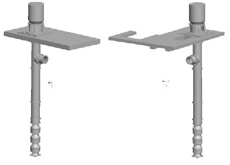
Figure 1. A solid model of one of the new vertical turbine pumps with a portion of the new structural foundation on the left and with a portion of the existing structural foundation on the right.
FEA Uncovered Potential Resonances Within the Running Speed Range
The pumps’ below-ground column modes and frequencies of vibration that were predicted by the FEA were similar. Therefore, any potential modifications to the column pipes to shift their vibration modes would be effective for the pumps that were located on either of the foundations.
However, depending on the foundation, the above-ground motor and motor-stand vibration modes that the FEA predicted differed markedly. This difference in the vibration frequencies was attributed to the variation between the stiffnesses of the two foundation structures.
Below ground level, the second bending mode structural natural frequencies of the column pipe, which were parallel to the discharge nozzles, had separation margins that were at least 18 percent above the maximum running speed.
However, the results of the FEA predicted that the natural frequency for this column pipe, in the direction perpendicular to the pump discharge, would fall within the pump’s operating speed range. This is illustrated in Figure 2.
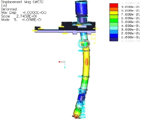
Figure 2. The pump column pipe second bending mode is shown with a color contour plot of the displacement superimposed over the exaggerated, deformed shape of the pump assembly. Features of the column in the undeflected position have been superimposed on the image to aid in seeing the deflected shape of the column. Though this pump is shown resting on the existing version of the foundation structure, the pump that was modeled as resting on the new foundation structure had a nearly identical vibration mode.
Excessive vibration would occur because the natural frequencies of vibration that were forecast by the FEA, 13 Hz in a minimum-submergence and 11 Hz for the case of maximum submergence, would be excited during the anticipated normal operation of the vertical turbine pumps at the station.
Potentially troublesome above-ground modes of vibration also were predicted by the FEA. This might occur with the pumps that were located at both foundation structures. The FEA of the pumps at the new section of the station predicted that the natural frequencies for the above-ground first bending modes of vibration would fall within 15 percent of the upper end of the pump running speed range. This condition would fail to satisfy the pump specification.
In addition, the FEA of the existing foundation indicated that the natural frequency for one of the above-ground first bending modes would land short of the desired 15 percent separation margin. See Figure 3.
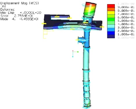
Figure 3. The above-ground, FEA-predicted, first bending mode of the new pump on the existing foundation is shown with a color contour plot of the displacement superimposed over the exaggerated deformed shape of the pump assembly. Features of the pump assembly in the undeflected position have been superimposed on the image to aid in seeing the deflected shape of the column.
Potential Solutions Investigated With FEA
Through additional FEA, a practical, potential solution to the predicted, below-ground pump vibration problem was investigated quickly. A 3/4-inch thick split steel plate was modeled between the bottom flange of the pump discharge and the floor of the station, to constrain the motion of the column pipe during the second bending mode.
The results of the FEA showed that this straightforward modification would increase the two offending natural frequencies of the pumps to between 21 Hz and 22 Hz. This is approximately 42 percent above the maximum pump operating speed. An acceptable margin of separation from the running speed range would be created when the split steel plates were included in the pump installations. If the split steel plates were implemented, the vibration frequency of the second bending mode of the pump column that was in line with the pump discharge direction also would increase. This would enhance the already-satisfactory margin of separation that existed for this vibration mode.
To address the potential above-ground pump vibration problems, thicker stiffening ribs were modeled on the motor stand, and an FEA was performed for the pumps that were located at both foundations of the station.
At the new foundation, the modified stiffening ribs were predicted to shift the offending natural vibration frequency higher. This would increase the margin of separation from the maximum running speed to 16 percent and enable the pump specification to be met.
However, the FEA results for the pump that rested on the existing foundation showed that the thickened stiffening ribs would not provide as much of an increased separation from the maximum running speed. This disparity was caused by the comparatively reduced foundation stiffness, which in turn was attributed to the access ports that were located in the floor of the building.
To alleviate this potential vibration issue, a concrete pillar was modeled in the existing building between the piping gallery level and the upper level, the location of the motor-stand and motor. The FEA of this proposed modification predicted that the addition of the concrete pillar would increase the magnitude of the above-ground natural frequencies and create an acceptable separation margin, as shown in Figure 4.
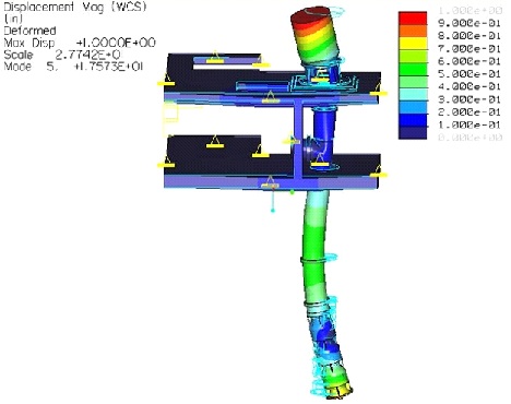
Figure 4. The above-ground, first bending mode of the new vertical turbine pump on the existing foundation structure (which was predicted by the FEA) is shown with the addition of the below-ground concrete support column. The mode shape is depicted with a color contour plot of the displacement that was superimposed over the exaggerated, deformed shape of the pump assembly. Features of the pump assembly in the undeflected position have also been superimposed on the image to show the deflected shape of the pump assembly.
The FEA results of the vertical turbine pumps were reported to the OEM, and the suggested solutions were also reviewed. Because the vertical turbine pumps were equipped with variable frequency drives (VFDs) and after considering the anticipated operating environment of the pumps at the station, the OEM suggested an additional solution to the pending vibration issues.
By programming lock-out ranges into the VFDs of the pumps after their installation, the undesirable vibration frequencies that were predicted to occur within the running speed range would be avoided.
Conclusion
The three new vertical turbine pumps were installed and the expansion of the station was completed. Figure 5 shows one of the newly installed OEM vertical turbine pumps within the finished pump station. As it was ramped through its operating speed range during the initial evaluation process, an increase in the vibration response of one of the pumps was measured at 13 Hz, where the FEA had predicted that a natural frequency of vibration of the column pipe would occur. This demonstrated the accuracy and the practicality of the finite element technique in this rotating machinery application.
Once the installation of the pumps was completed and the on-site performance of the pumps was verified, the pump OEM programmed lock-out speed ranges into the VFDs of the pumps, which prevented the operation of the pumps at the speeds during which the undesirable resonances had been predicted to occur.
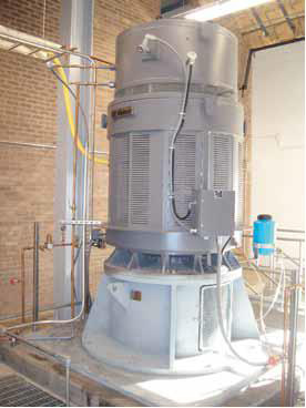
Figure 5. The above-ground portion of one of the new vertical turbine pumps that were installed within the new section of the expanded Kings Bluff Raw Water Pump Station
By performing the FEA prior to the installation of the vertical turbine pumps, several natural frequencies of vibration were identified. This vibration could have adversely affected the long-term reliability of the pumps. The FEA also enabled the virtual implementation of potential solutions to the anticipated vibration issues. This process was far more efficient than a trial-and-error, onsite implementation of experimental solutions.
If the pumps had not been equipped with VFDs, the structural modifications that were suggested through the FEA would have been implemented to ensure that the unwanted vibration would not occur. The pump OEM was able to anticipate correctly the potential vibration frequencies because of the FEA. To avoid the vibration problems, the OEM programmed the pump VFDs to lock out the undesirable vibration frequencies that fell within the pumps’ running speed range.
Pumps & Systems, December 2010