


A combination of two seal types provides the most reliable results.
Today's rotary shaft fluid sealing applications typically involve three types of sealing technologies: contact lip seals, labyrinth seals and mechanical seals.
Contact Lip Seals
The oldest and most cost-effective technology is the contact lip seal, usually made of an elastomeric or a polytetrafluoro- ethylene (PTFE) lip material. Under aggressive conditions, the contact lip may be subject to premature failure due to sporadic dry running conditions. Heavily contaminated environments can cause excessive wear to the sealing lip and the surface of the shaft.
Labyrinth Seals
The second sealing technology, the labyrinth seal, is usually comprised of a machined rotor and stator retained with a bolt-on flange or O-ring compression. The typical labyrinth seal is designed for non-contact, virtually eliminating wear on the internal components of the seal. Through the use of torturous paths and drain ports, external contaminants are expelled prior to entering the lubrication cavity.
On the seal's other side, lubrication that travels into the seal assembly is directed to the lubrication cavity to prevent its escaping to the external environment. If it becomes flooded, this non-contact seal will allow lubrication to flow through the seal assembly and leak.
Mechanical Seals
The third sealing technology, the mechanical seal, uses extremely hard and finely ground surfaces (two to three helium light bands) at the dynamic interface, which is typically loaded by a spring mechanism. While this type of seal is very effective in aggressive environments (high pressure, high temperature, extreme abrasives, etc.), it is also the most costly. In addition, it requires a delicate set-up with a flush or barrier fluid to supply lubrication to the finely ground dynamic surfaces.
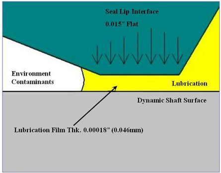
Figure 1. Close-up view of seal lip to shaft interface.
Hybrid Seal
Until recently, the only effective sealing options for flooded applications in which the oil level is above the bottom of the bore diameter were a contact lip seal or a mechanical seal. However, a new hybrid technology combines the flooded sealing capability of a contact lip seal and the contamination deterrence of a labyrinth seal. This seal is easily installed, eliminates shaft and other equipment wear caused by aggressive contaminants, can continue to perform if cycled from full to no lubrication and offers extended service life versus traditional contact lip seals.
A major challenge in the development of this new seal was the contact lip seal technology. Basic elastomeric lip seals allow the sealing lip to ride on a thin film of lubricant approximately 0.00018 inch thick (Leewen & Wolfert, 1997).
When designed properly and in a lubricated state, the seal lip forms a small, hydrodynamic pump, approximately 0.015 inch wide at the lip-to-shaft interface that constantly circulates fresh lubricant under the lip to shaft interface. See Figures 2 and 3 (R.F. Salant, 1996). This is why a seal in a well-lubricated state with little or no contamination can last for years with little wear. In aggressive environments, the elastomer can be abraded away, so PTFE is sometimes used as an alternative material for better abrasion resistance and a lower coefficient of friction for dry running conditions. Unfortunately, PTFE is a plastic material that lacks an elastomer's elastic properties. This prevents it from forming the necessary micro-asperities to create the hydrodynamic pumping action at the seal lip-to-shaft interface. The new hybrid seal allows a PTFE contact lip to effectively seal flooded and oil mist conditions. Instead of relying on elastic properties for hydrodynamic pumping, a special-geometry PTFE contact lip allows it to ride on the shaft under dry running conditions. A biconcave chamber between the contacting surfaces creates a pressure differential to retain the lubricant behind the seal when it is flooded. This geometry and a precision-ground surface, result in a high-performance PTFE contact lip seal. These components were incorporated into a bearing isolator rotor/stator labyrinth configuration (See Figure 4). The labyrinth seal faces the external environment, diverting contaminants away from the PTFE seal to provide IP56 ingress protection. On the internal lubrication side, a small contacting face seal between the rotor and stator assists in diverting lubricant back to the sump, providing twice the retaining power of traditional bearing isolators and facilitates manual installation without an arbor press or other tools.
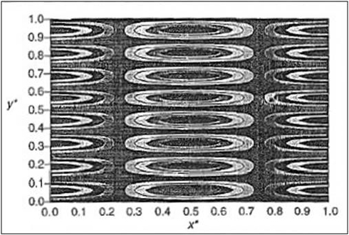
Figure 2. View of elastomeric element prior to shaft rotation and hydrodynamic pump formation.
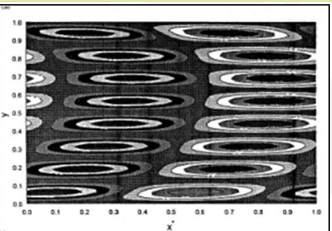
Figure 3. View of an elastomeric element after shaft rotation showing micro-asperities that create hydrodynamic pumping.
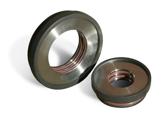
Figure 4. Flooded bearing isolator
Pumps & Systems, September 2011