


The term carbon footprint has become synonymous with greenhouse gas (GHG) emissions and climate change. Carbon footprint commonly refers to the volume of greenhouse gases, the most prominent of which is carbon dioxide, which are emitted by an organization, event, process or product.
Because of climate change concerns, coupled with rising energy costs and dependency on non-renewable and foreign sources of energy, the related term energy footprint is entering the vernacular of industry and regulatory organizations. The U.S. Department of Energy (DOE) developed energy footprints to help target energy saving opportunities in the manufacturing industry. They map the flow of energy supply and demand in facilities and show where and how the energy was used and lost from inefficiencies. The DOE uses energy footprint maps such as the one in Figure 1 to track the flow of energy supply, demand and losses.
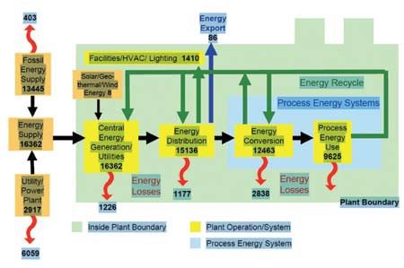
Figure 1. Manufacturing plant energy footprint. Source: Industrial Technologies Program, U.S. Department of Energy. Analysis based on 2002 Manufacturing Energy Consumption Survey (Energy Information Administration) data.
Pumping Systems
With the growing focus on the energy footprints of industrial facilities, pumping systems have received significant attention. DOE data indicate that pumping systems consume almost 20 percent of the world's electrical energy demand. To help pump users address this issue, the ASME recently published Standard EA-2-2009, Energy Assessment for Pumping Systems. The Hydraulic Institute (HI) has also focused attention on energy improvements with the Pump Systems Matter educational initiative.
Sealing Systems
Sealing systems are often neglected as contributors to the pump system energy footprint. For most applications, a well engineered sealing system can provide reliable, low emission performance with an insignificant energy footprint compared with the overall pumping system. However, poor selection and implementation of the seal configuration and associated seal support systems can result in an energy footprint that approaches, or in some cases exceeds, that of the pump.
This is the first in a series of four Sealing Sense articles designed to explain how the selection and application of sealing systems affect their energy footprint. The series will provide guidance on best practices to minimize the sealing system's energy footprint size.
This first article provides an overview of the sealing system energy footprint and the energy losses from the interaction between the mating seal faces. The September article will focus on the impact of thermal inputs to maintain the fluid temperatures for high temperature processes. The October issue will address the energy impact of removing diluents introduced as seal flush fluids from the process stream. The final installment will cover the impact of pump shutdown, repair and re-commissioning on sealing system reliability and the energy footprint.
Seal Face Interaction
Mechanical seals operate with one of three mating face lubrication regimes. They are boundary lubricated, full fluid film and mixed lubrication.
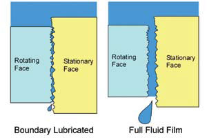
Figure 2. Seal face lubrication regimes
Boundary Lubricated
For seal faces operating in this mode, the mechanical load is transmitted almost entirely by contact of the asperities on the surfaces of the rotating and stationary seal rings. This contact consumes electrical energy from the pump driver and converts it into thermal energy from friction between the mating sealing surfaces. The amount of power "lost" at the seal faces is calculated by the formula:
Q (in Watts) = π(ro2 - ri2) [po(B-½) +ps] Vƒc
Where:
ro = Seal face outer radius (m)
ri = Seal face inner radius (m)
po = Pressure at the seal face outer radius (Pa)
ps = Pressure on the seal faces from the spring forces (Pa)
B = Seal balance ratio
V = Sliding speed at the mean radius of the seal faces (m/s)
ƒc = Friction coefficient between the seal faces
The seal balance ratio represents the portion of the hydraulic pressure from the fluid sealed that provides a force pushing the seal faces closed. The simplest seal designs are unbalanced but can result in thermal energy generation more than two times that of a balanced seal. For a typical single balanced refinery seal operating at 3,600 rpm and 20 bar (300 psi) on a 50 mm (2 in.) shaft size, the thermal power per this formula is 970 Watts (3,300 Btu/hour).
Full Fluid Film Lubrication
This regime occurs when the mating seal faces are separated by a thin film of fluid, and no physical contact exists between the sealing surfaces. Hydrodynamic seal face topography can be used to create
the separation forces that enable a seal to operate in a full fluid film mode. For liquid lubricated seals, the associated energy losses from viscous shear can still be noteworthy, especially when the fluid between the seal faces has a higher viscosity. Operation in this regime will also result in higher leakage levels that must be considered for each application.
For gas lubricated dual seals (where an inert gas barrier [typically nitrogen] provides the fluid between the seal faces), leakage of the barrier gas into the process stream and the atmosphere is usually well tolerated. Because of the low viscosity of gases, the thermal energy generated by viscous shear of the gas between the seal faces is almost negligible. Figure 3 shows the significant differences between the power consumption of full fluid film gas lubricated and mixed lubrication oil lubricated dual seals.
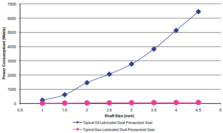
Figure 3. Comparison of power consumption for dual pressurized oil verusus gas seals.
Mixed Lubrication
This regime is similar to boundary lubricated, but the fluid in the gap between the seal faces supports a portion of the contact forces between the seal faces. The thermal energy generated from contact friction between the seal faces is decreased with mixed lubrication, but the additional source of thermal energy from viscous shear of the fluid film between the seal faces becomes more significant. The magnitude of the viscous shear thermal energy increases in direct proportion to the viscosity of the fluid between the seal faces. For dual seal applications, where the barrier fluid provides the lubrication between the seal faces, lower viscosity barrier fluid can significantly impact the sealing system energy footprint.
Auxiliary Systems
The seal face thermal energy footprint is further magnified when auxiliary piping systems with heat exchangers are required to remove the thermal energy generated at the seal faces. The heat exchangers often require circulation of cooling water and operation of cooling towers or similar devices to recycle the cooling water. Dual gas seals have the advantage of not requiring any kind of cooling equipment to remove thermal energy since low levels of heat are generated at the seal faces.
Conclusion
The energy footprint from the interaction of the mating seal faces can be minimized by the following:
- Always employing balanced seal designs
- Selecting a barrier fluid with the lowest viscosity for the application
- Using seal designs operating in a full fluid film mode when appropriate
- Applying gas lubricated dual seals when application conditions allow
These basic seal system considerations can significantly reduce the energy footprint of the seal face interaction. Their contribution to the overall sealing system energy footprint should be considered after review of all the components of the sealing system's energy footprint. The next Sealing Sense articles will focus on considerations related to configuration, operation and maintenance of the sealing system, which can greatly impact the energy footprint.
Next Month: What is the sealing system energy footprint associated with maintaining the process fluid temperature?
We invite your questions on sealing issues and will provide best efforts answers based on FSA publications.