


An innovative sealing solution improves safety and increases pipeline flexibility and product delivery.
In 2007, a new fractionation plant was added to a pipeline originally built in 1980 for a major gulf coast firm that specializes in production, transportation and storage of liquid hydrocarbon and natural gas. The New Mexico plant was designed to separate liquefied petroleum gas (LPG) and transport it to South Texas.
The original end user solution considered incorporating 24 new pumps to efficiently transport ethane, butane, propane and natural gasoline. However, a unique sealing solution involving highly pressurized dual seals with an independent pressurization and cooling system paid huge dividends. This approach not only eliminated the need for a dedicated pump and driver for the lightest fluids, but also increased flexibility and product delivery, reduced operating costs, as well as eliminated fugitive emissions to the atmosphere. All this was accomplished with the use of the existing pumps. The pipeline consisted of sealing applications with pressures up to 1440 psig (100 bar) and speeds up to 4500 rpm.
Solution
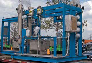 |
| Sealing Solution for the LPG Pipeline |
The sealing manufacturer sought a solution that would give the energy services company the flexibility to pump multiple fluid streams at various operating points. In many cases, light hydrocarbon applications are sealed with single and dual non-pressurized seals. However, these seal arrangements are not suitable for handling the changing fluid properties of this specific pipeline system. Ethane, the lightest of the fluids, has the most adverse effects on mechanical seals because of its poor lubricating properties. As such, a dual seal with an independent pressurized sealing system was chosen as lubrication of the seal faces is not affected by the varying fluid properties of the liquids being transported through the pipeline. Instead, lubrication of the seal faces is assured by a clean, environmental friendly barrier fluid that is pressurized, circulated and cooled.
A compact cartridge mechanical seal was needed because of the age and design of the 1970-era pumps, complete with dimensionally limited seal chambers when compared to those that meet current pump and mechanical seal standards. Understanding the existing pump limitations was important as it forced compromises in the design of the seal faces and other parts. Investigating and accounting for each limitation was vital to ensure that everything fit and that costly and, at times risky, pump modifications were avoided. Compromises in seal design at these pressures, under cyclic operation could have affected the pump's performance if not carefully evaluated. Although the challenges were numerous, EagleBurgmann engineers solved the problem with a simple and compact seal design that fit all of the pumps on the pipeline.
The operating range of the applications combined with the age of the pumps, safety requirements, environmental consequences of sudden seal failures and the remoteness of the pumping stations demanded a highly automated and reliable auxiliary system. Low barrier fluid and power consumption of the mechanical seals were critical because the system would require manual refilling and cooling water was not available at the pumping stations.
With minimal interruption to the pipeline, it was essential that the solution would ensure delivery of different products to South Texas beginning April 2007. With a tight timeline, the manufacturer planned to design and build the seals and systems.
Implementation
In API682 terminology, the seal design is a 3CW-FF (arrangement 3, contacting wet lubrication, face to face configuration). The support system is a special version of API plan 53B. Consistent low leakage rates and friction were achieved by utilizing seal faces that are extremely stiff, adding face lubrication enhancement features and by applying the optimum materials. Shrink fit seal face technology is particularly suitable for high-pressure applications because the weak carbon face is shrunk in a heavy-duty stainless steel housing and supported at the inside diameter with a metal reinforcing ring. The rotating silicon carbide seal face is common for both stationary seal faces and is also shrunk in a stainless steel ring that incorporates a pumping device to circulate and cool the barrier fluid. Small circular grooves, also called hydro-grooves, are machined into the silicon carbide face to enhance lubrication. Shrunk fit seal faces furthermore eliminate the potential for major product releases as the faces cannot break.
 |
| Carbon face shrunk into a heavy-duty stainless steel housing |
The purpose of the auxiliary system is to control barrier fluid pressure, provide cooling to the seal faces and store barrier fluid for leakage make-up of the seals. Failure to comply with any of these requirements may cause seal failure.
Based on operating conditions and other factors, a derivative of API plan 53B was selected. With few moving parts, it requires little maintenance, consumes virtually no energy and allows for monitoring of the seal integrity. The ability to detect the onset of a failure early is key to avoiding major releases of barrier or pumped fluid.
In the Field
Initial field experiences were mixed. Early seal failures were threatening the reliability expectations as specified in the project goals. However, though start-up failures did occur on several pumps, they were not related to the behavior or performance of the sealing faces. Dynamic O-ring wear was the major cause of early failures. In some stations, failures occurred after only a few weeks of operation, while others ran without any trouble and even exceeded barrier fluid consumption expectations. The cause for the rapid O-ring degradation was excessive run-out caused by shafts that were so worn that the original tolerances were lost, which resulted in wobbling seal faces. Large pressure differentials accelerated wear of o-rings and their sealing surfaces.
Custom sleeves were made to fit the worn shafts as a containment solution. Long-term, the solution is to replace or rework the shafts to their original tolerances during planned maintenance outages. Quite a few modifications were made to the seals to cope with the adverse equipment conditions of several pumps.
In some stations, problems occurred with specific modes of pipeline operation that caused pressure reversals on the inboard sealing faces. In these cases, a controlled shut-down occurred in response to early warning signs in combination with the ability of the inboard sealing faces to seal in reverse pressure operation. The solution to avoid pressure reversals was to raise the barrier pressure to the maximum discharge pressure of the pump. In one case, the seals failed because of an instrument failure that caused a complete system malfunction. Excessive spill of barrier or pumped fluid, however, was avoided. Although annoying from a reliability perspective, these failures actually proved that from safety and environmental perspectives, the seals and systems performed appropriately.
Conclusion and looking forward
Overall, the new sealing solution—in use since 2007—is outperforming the old method by a significant margin considering reliability, safety, energy and environmental perspectives. It increased pipeline flexibility and simultaneously improved overall product delivery. Continuous improvement in pipeline operations will increase both reliability and product delivery performance. Further, this sealing system has been successfully applied to other pipeline projects around the world.
Today, state-of-the-art seal face technology enable dual-pressurized mechanical seals to operate reliably up to 3500 psig (250 bar) and triple seals up to 7350 psig (500 bar), regardless of the fluid being pumped. In the past, such levels were thought impossible.
Pumps & Systems, November 2010