


Vertical turbine pumps have multiple components that may make alignment complicated in American Petroleum Institute (API) and industrial applications. Tolerances cannot be made tight enough to ensure proper alignment because the required tolerances cannot be achieved by manufacturing accuracy alone. It takes skill, time and patience to make the minor adjustments required to ensure proper alignment. When aligning the components of a vertical turbine pump, end users must understand and evaluate key considerations for the following designs:
- VS-1 tank mounted vertical turbine booster pump (single casing) utilizing a vertical P-Base driver with integral thrust bearing design
- VS-6 vertical turbine booster pump with suction barrel (double casing) utilizing a vertical P-Base driver with integral thrust bearing design
For further definitions of these two pump types, please refer to API 610 11th Edition paragraph 9.3.10 and 9.3.13.
As with any pump installation, end users should pay close attention to the pump application and where the pump is operating on the performance curve. A properly sized pump can provide years of trouble-free service and increase the mean time between failures caused by wear and induced vibration issues. The pump manufacturer will typically specify the preferred and allowable operating ranges on their performance curve as well as minimum continuous stable flows.
Pump and driver alignment is also critical for achieving maximum life of the driver, pump bearings and mechanical seal assembly. This article will focus on the shaft alignment of the driver, discharge head, shaft coupling and mechanical seal housing for pumps (and pump cans) that are installed and leveled according to manufacturer recommendations.
Alignment
The pump driver may consist of an electric motor, vertical gear or steam turbine that incorporates a vertical solid shaft design mounted on the pump’s discharge head. The vertical solid shaft driver must be supplied with special shaft and base flange tolerances. API 610 11th Edition specifies the tolerances in Figure 1. The maximum shaft runout and shaft to driver face perpendicularity of 0.001 total indicated runout (TIR) are most important. The 0.005 TIR maximum axial float may be achieved in most cases, but some extra high thrust designs may require greater axial float.
The pump discharge head should be welded according to specification requirements. If it is constructed of carbon steel, a post-weld heat treatment (PWHT) process is recommended after fabrication and prior to machining to prevent warping after the final machining process. Users should give special consideration to the driver to discharge head female/male register fit, typically referred to as the National Electrical Manufacturers Association (NEMA) driver “AK” dimension.
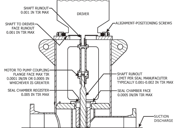 Figure 1. The drawing shows the critical dimensions. Ensuring the proper seal alignment between the pump and driver is the best safeguard for prolonging seal life and maximizing the mean time between repairs.
The discharge head should be designed to allow the driver to freely move in any horizontal direction—at least 0.020 inch/inch (in/in) TIR relative to the vertical axial centerline of the discharge head. Instead of tapped holes, the discharge head should incorporate through bolting for mounting the driver. This design element will facilitate additional horizontal movement necessary to achieve proper alignment. Alignment positioning screws are required for any driver that exceeds 500 pounds per API 610 11th Edition, section 9.3.8.3.2. When alignment-positioning screws are incorporated into the discharge head design, the register fit between the discharge head and the driver must have open clearances. A register with greater clearance is helpful because it allows the driver to be roughly positioned. Alignment-positioning screws for drivers under 500 pounds are also recommended to facilitate alignment.
The driver should not be aligned using shims, especially if the pumps are to be used with electric motors that have variable frequency drive systems (VFDs) because this setup will change the resonant frequency of the driver/discharge head structure.
A rigid flanged spacer coupling must be supplied with special tolerances. API 610 11th Edition specifies these tolerances in section 9.3.8.2, which requires the coupling faces to be perpendicular to the axis within 0.0001 in/in of face diameter or 0.0005 in/in TIR total, whichever is greater.
Manufacturing
The fabricated discharge head should be relieved of stress once welding is complete and prior to machining. During the machining process, stresses induced by welding can result in runout. The runout issues can affect the perpendicularity of the motor mounting flange and/or the concentricity to the seal chamber bore.
The seal chamber must be supplied with a registered fit. This registered fit must be concentric to the shaft and have a 0.005 in/in TIR per API 610 11th Edition section 6.8.4. The seal chamber face should have a runout of 0.0005 in/in of seal chamber bore TIR per API 610 11th edition section 6.8.5.
The pump and driver should be coupled, and runout should be inspected. The shaft runout must be within the maximum allowed by the seal manufacturer for that particular mechanical seal. This value is typically 0.001 to 0.002 in TIR. Users should also check the seal register and face runout. Documentation of the inspection should include the pump and driver serial number along with measurements. The AFS coupling should be tagged for use on the specific pump and match marked. These steps will ensure proper assembly orientation.
Installation
Cleaning all surfaces before attempting to align the pump and driver is vital. If alignment was not performed at the factory, the keys of the AFS couplings may need to be deburred, and the flange faces may need to be cleaned to remove any protective coating.
A dial indicator connected from the driver shaft should be used to obtain a TIR within 0.005 in/in at seal chamber register. The driver to pump coupling should then be installed to verify that the shaft TIR does not exceed the limits recommended by the seal manufacturer. If the shaft runout cannot be achieved, a slight adjustment to the driver may be required. The pump/driver coupling may also need adjustment. Rotating one half of the coupling may reduce perpendicularity tolerance stack-up, which can cause problems. If the coupling must be installed in a particular way, it should be match marked. Once the shaft runout has been verified, the seal chamber register should be rechecked to confirm that it is still acceptable, and the seal chamber face runout must also be checked. Once the alignment is verified, the mechanical seal can be installed.
Troubleshooting
If the runout tolerances cannot be achieved, end users can consider the following troubleshooting checks. The easiest process to check first is the pump to driver coupling. Each coupling part can be checked both individually and as an assembled unit. If this process identifies a runout issue, the coupling can be reworked or replaced.
In many cases, the seal housing can be removed without removing the motor. Once the seal housing is removed, the runout can be inspected and verified. If the seal housing has an excessive runout, this component should be reworked or replaced. If the runout issue is not found in the seal housing, check the runout between the driver shaft and the seal housing bore on the discharge head. If excessive runout exists at this check, the discharge head is the source of the issue.
Checking the shaft runout of the pump driver can be achieved without removing it. If everything to this point has been found to be satisfactory, the driver will need to be removed and the shaft to the driver face checked for perpendicularity. Pumps that do not have alignment-positioning screws will also need to have the register concentricity inspected with relation to the shaft. If these items have been checked and found acceptable, the issue is with the pump—either the discharge head or the pump shaft.