


Recently, I received a call from a plant operator in Ohio. He said, “We have a big contract from a customer to supply multiple oil heating systems and have just completed the first unit. It is ready to ship. These systems are assembled on mobile skids with a centrifugal pump that transfers oil from the tank to the filling containers. We designed the system for 30 gallons per minute (gpm) and tested each system at the shop’s test facility. When we set it up on a mobile unit and connect the suction line to the supply tank, we get different results. What’s wrong?”
Steve provided the system details, which were:
- The pump is a Goulds’ 1 x 1.5-6, with a 5.12-inch impeller—outside diameter.
- The system pumps oil through a heat exchanger and then to fill containers.
- The process is mobile and has a short suction pipe, which the customer connects to the large tank to supply the filling stations.
- The pipes are sized large, especially the suction pipe, to ensure that friction losses are negligible.
“We will test each unit at the shop with a flow meter,” Steve said. “In the field, no flow meter will be used. The customer will estimate the flow based on the pressure gauge reading. Each unit is supplied with a certified pump curve (see Figure 1), so estimating the flow should not be easy.”
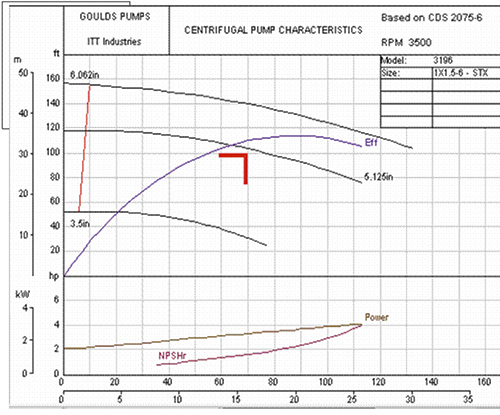 Figure 1. Pump curve. Source: Goulds Pumps
That sounded simple enough, and I drew a sketch while listening (see Figure 2). Steve continued, “I know we are getting 30 gpm because I calibrated our shop flow meter myself and recalibrated it to make sure. The discharge gauge reads 44 pounds per square inch gauge (psig), which converts to about 118 feet (our oil is 0.86 specific gravity). If I use this number and get the flow at that head from the pump curve, I get about 30 gpm.”
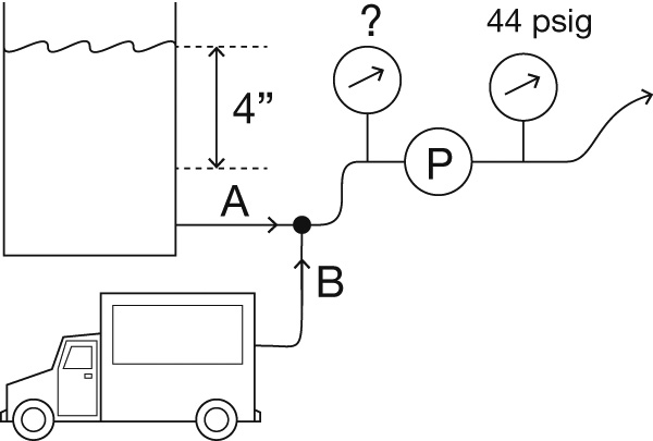 Figure 2. Simple sketch of the mobile oil pumping system
“So, what’s the problem?” I asked. “You get the correct flow, and your gauges measure the pressure that corresponds to the pump curve. I assume the suction gauge reads about zero, so the 44 psig is the differential across the pump.”
“That’s the problem. The suction gauge shows about 7 psig. The differential is 44 minus 7, which is 37 psig. This is nearly 80 gpm according to the curve.”
Steve was right. According to the pump curve, the head corresponding to 37 psi differential pressure was:
37 x 2.31 / 0.86 = 99 feet
I consulted a Goulds’ pump catalog curve. At 100 feet, the pump should move about 80 gpm. Was his meter wrong? I questioned Steve about the suction side.
“It is simple. We have a tank that is always filled, about 4 feet above the pump inlet. I know about air entrapment and designed the tank to make sure that no air is drawn in. Inside, the surface is nice and smooth with no vertices.”
With this new information, I recalculated the numbers and could find no smoking gun. However, he said that the tank level was 4 feet. If so, that is only 4 x 0.86 / 2.31 = 1.5 psi. Even with small losses on the suction side, the gauge should read even less, perhaps 1 psig, but certainly not 7 psig. What was causing the 7 psig reading? I thought I had the answer, so I called Steve back.
“I bet the problem is the suction pipe,” I told him. “You must have one or more short elbows in front of your pump.”
“Yes…you don’t have much room to maneuver there. Why?” Steve asked.
“I think what you have is swirl, which is created when sharp-radius elbows are too close to the pump inlet. You get the right flow, but the suction gauge registers higher pressure. It picks up static pressure and a dynamic, rotating component. The result is artificially high suction readings. Also, your pump’s best efficiency point (BEP) is about 90 gpm at this impeller diameter, and you are operating at 30/90, which is 33 percent of BEP. When a centrifugal pump operates at a low flow rate, it experiences back flow, which is a swirling flow that makes the impeller tip move. This could also be contributing to the problem.”
Steve wondered how to correct the problem. He had two options. First, he could straighten the suction piping by eliminating elbows or inserting flow straighteners. The other option was putting another straightener between the gauge and the pump inlet. If he installed a honeycomb or simple cross-member between the suction gauge and the pump, the backflow would be broken down, and the swirling component would disappear.
I had one more suggestion. “Since you know what is going on, why change anything? Accept that the suction gauge should read about zero. Then develop a calibration curve, plotting the pump flow versus the discharge pressure. Then the customer would simply read the discharge pressure (no suction reading), and read the flow from the curve. While not perfect, it should work.”
Steve thought I was right wanted to test the anti-swirl idea to make sure. He later called back. The swirl theory was right, and he was happy. Since several units had already been shipped, I assumed his supervisor was happy, too.