


A unique gas seal design increases reliability in HF alkylation unit pumps.
A major northeast oil refinery recently integrated advanced dry gas sealing technology into several pumps on its Hydrofluoric Acid Alkylation Unit in an effort to meet current American Petroleum Institute (API) requirements for mechanical seals in these services and to increase reliability while complying with local state and federal fugitive emissions guidelines. Hydrofluoric acid (HF acid) is a solution of hydrogen fluoride in water. It is a colorless, odorless and extremely corrosive solution found in many oil refineries, where it is primarily used as a catalyst in the production of high octane gasoline blending stock.
Due to the toxicity of this fluid, meeting inherent safety measures is required when handling the fluid and handling the equipment associated with it. While each plant has its own safety guidelines in place to manage HF acid, it is universally accepted throughout the industry that minimized personnel exposure to this substance is of paramount concern.
Many improvements have been made to several process pumps in the refinery's HF Alkylation Unit. These improvements provide additional layers of personnel protection while at the same time increasing the reliability of the mechanical seals installed in these services.
The Problem
The pumps in question were originally sealed with single-cartridge, pusher-style mechanical seals using an external flush fluid injection as the primary seal face lubricant. This method of flushing is categorized as an API Flush Plan 32. The use of a single cartridge mechanical seal in this hazardous service is not desirable for obvious reasons.
One is that any significant leakage past the seal faces will result in loss of containment of the flush medium and potentially the release of HF acid containing process fluid to the atmosphere.
 |
| Figure 1. Old piping layout |
To help mitigate potential seal leakage to the atmosphere, the low-pressure side of each seal was connected to the unit's flare header. Additionally, a low-pressure nitrogen purge was added to each mechanical seal a few years prior in an effort to dilute the primary seal leakage and lower detectable emissions to the atmosphere.
While the system functioned adequately for several years, reliability issues were associated with several of the pumps specifically related to inadequacies of the external flush supply source, resulting in premature seal failures in the majority of these services.
In some extreme cases, the average mean time between repair (MTBR) of the mechanical seals was six months. In addition, the interconnecting seal flush and vent to flare piping around each mechanical seal was hard piped with flanged joints. This configuration made access to each pump for day-to-day maintenance and condition monitoring extremely difficult.
The refinery, working closely with the preferred mechanical seal supplier for the plant, set out to implement a sealing solution, in each of the services in question, that would not only supply an enhanced seal design that would limit personnel exposure to the process fluid but would also improve reliability and satisfy applicable environmental regulations.
Solution
In reviewing the application specifics, the mechanical seal supplier for the plant offered a unique, yet validated over the last 15 years, sealing solution that satisfied the project requirements. The selected seal design is categorized as an API 682 Category II seal and, more specifically, a dual unpressurized gas buffer tandem seal. The driving force behind the selection was two fold:
The selected design could re-use the entire existing support infrastructure in place (Plan 32 flush, nitrogen purge and vent to flare piping).
The mechanical seal vendor had an extensive operating history to reference regarding the use of the specific seal design in HF acid service.
The mechanical seal design uses a wet contacting seal as its primary seal, a non-contacting, I.D. pressurized, outward pumping gas seal as its secondary seal and a segmented carbon throttle bushing as a final seal between the outboard seal and the atmosphere. The API Flush Plan designation for this seal support system is categorized as an API Plan 32 / 72 / 76. In this configuration, the primary seal is exposed to the process fluid, which in this case would be the external flush media (propane, isobutane, etc.).
The secondary seal is supported by a low pressure purge of nitrogen (Plan 72), with primary seal leakage vented to the unit's flare system (Plan 76). It is the specific design nuances of the proposed seal, particularly the use of spiral-groove seal face technology that makes the solution unique.
In normal operation, the flush leakage past the primary seal is sealed by the dry running, non-contacting seal that is designed to compress moisture-free nitrogen gas from the inside diameter to the outside diameter into the outboard cavity. The mixture of the nitrogen with the vaporized flush leakage is then vented to the unit's flare system. Nitrogen is supplied outboard of the dry tandem seal between the bushing, which restricts its flow.
The dry running seal faces incorporate a series of partial spiral grooves, which are designed to operate on a thin film of gas. The grooves are configured to pump from the inner diameter (ID) to the outer diameter (OD) of the seal faces. See Figure 2. The nitrogen quench supply ensures an inert spiral groove film, which results in a small amount of nitrogen leakage to the unit's flare system.
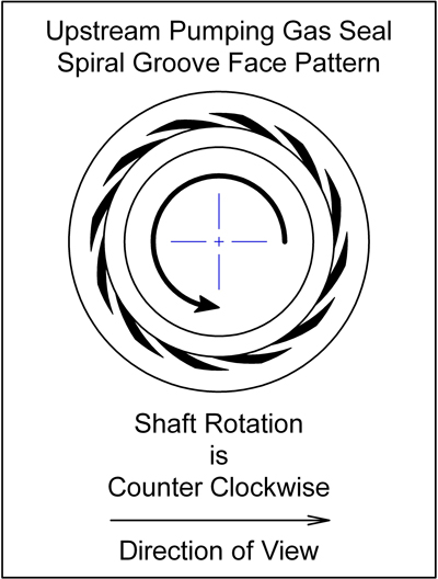
Figure 2. Spiral groove face pattern
Vapor leakage past the inboard seal under normal operating mode is completely isolated by the nitrogen quenched seal and cannot escape to the atmosphere. Therefore, all emissions are directed to the flare system through the gland vent. An inclusion of an orifice in this vent line allows the restriction of more significant levels of leakage such that a pressure rise will result. A pressure switch between the seal and the orifice detects a pressure rise associated with primary seal failure should it occur.
Nitrogen leakage of the gas seal will enter the flare system header line through a vent in the gland plate while nitrogen leakage across the bushing will be released to the atmosphere. The bushing also serves as an additional containment seal in the unlikely event that both the primary and secondary seals fail. See Figure 3.
To address the reliability concerns with the existing Plan 32 flush fluid, a new dedicated flush header was installed in the center of the unit's pump alley with take off points for each mechanical seal. The new flush header was carefully sized to reduce system friction losses, assuring that the flow requirements of each seal are met at all times.
Another concern was that the source pressure was only marginally greater than the seal cavity pressures in some services, which meant adequate cooling flow rate to those mechanical seals could not be achieved. The cause of the subsequent pressure drop in the flush pressure was attributed to a downstream cooler whose tubes were significantly plugged with sludge and scale. To alleviate this concern, a new tie in point for the flush supply was identified upstream of the problematic cooler. The cooling of the flush fluid could be achieved with dedicated heat exchangers at each mechanical seal. This significantly improved the reliability of the primary seal flush.
In an effort to further enhance the functionality of the seal support system, it was proposed that the flush piping could be improved by centralizing each pump seal's flush, purge and vent to flare piping off the pump base plate using a panel mounted configuration for each circuit.
Each seal panel arrangement would be mounted away from the pump. The connections to and from the mechanical seal and panels would be made up with tubing while tie-in's upstream and downstream of the panels would be hard piped. The individual panel component materials of construction were selected for optimum corrosion resistance based on the aggressive nature of the process fluid and vapors.

Figure 3. Seal support piping
Prior to project implementation, maintenance and condition monitoring accessibility was limited. In mounting the bulk of the flush, nitrogen purge and vent to flare components for the mechanical seal away from the pump baseplate, the area around the pump was immediately made more accessible for routine maintenance and condition monitoring activities. See Figure 5.
Conclusion
Installation of the proposed mechanical seal design and support piping modifications began in the first quarter of 2009, beginning with installation of the improved mechanical seal design in the poorest performing pumps. Since the modifications were implemented in these services, the MTBR has already increased from six months to one year, with continued emissions compliance being achieved.
The project was finally completed in the fourth quarter of 2010, with no seal failures to report to date. The revised seal design continues to keep allowable emissions well below the mandated levels.