


When designing a process valve and piping system, it is necessary to both choose the right valve configuration and appropriately select the automation configuration. There are various types of valves, which sparks the following questions: Should they be manual or automated? If they are manual valves, are they out of reach or easily accessible? If they are automated valves, what type of automation is necessary? Is a supervisory control and data acquisition system (SCADA) required for the automation? Are any automated valves going to be modulating? Are there any critical automated valves that will require a failsafe option in case of a system failure, power loss or other natural catastrophe? All these questions must be considered when designing the process piping system.
Valve Selection
One of the first steps of the process design is selecting the appropriate valve type. A resilient seated butterfly valve would be an acceptable selection for media that may have suspended particles and/or higher flow rates, such as in filtration. A butterfly valve with a non-wetted body is an excellent solution for corrosion resistance.
Weir-type diaphragm valves would be a suitable solution for a slurry or a throttling application, such as pressure sensing or flow metering. The linear flow characteristic allows for manageable flow rates and precision flow control for the most precise applications.
A ball valve would be an acceptable selection for clean filtered media with no suspended particles. When used in a sodium hypochlorite application, an isopropyl alcohol application or any application where off-gassing may occur, using a ball valve with a vented hole designed specifically for these applications should be considered.
Valve Considerations
Selecting the correct valve for an application involves many considerations to ensure the valve will meet the application requirements, such as thermoplastic material, chemical compatibility, pressure and temperature ratings, size and connection type, flow rate and pressure drop and regulatory compliances.
- Thermoplastic material: Different thermoplastic materials, such as polyvinyl chloride (PVC), chlorinated polyvinyl chloride (CPVC), polypropylene (PP), polyvinylidene fluoride (PVDF) or polytetrafluoroethylene (PTFE), have varying degrees of temperature tolerance, chemical resistance and strength. It is critical to choose a valve material that is compatible with the process flow media and the operating conditions of the system.
- Chemical compatibility: Verify the chosen thermoplastic material is resistant to the chemicals, acids and bases present in the system to prevent degradation and corrosion of the valve. Always check the chemical compatibility chart provided by manufacturers to make an informed selection.
- Pressure and temperature ratings: Confirm the operating pressure and temperature range of the system to ensure the selected thermoplastic valve meets the requirements. Making the correct selection will prevent failures and deformation of the valve.
- Size and connection type: Ensure the valve size matches the pipeline dimensions, the connection type (flanged, threaded, solvent cement) and aligns with the piping system to facilitate proper installation.
- Flow rate and pressure drop: Ensure the flow characteristics of the valve and its effect on pressure drop within the system do not negatively impact the process. Ensure the valve’s flow (Cv) meets the system’s flow rate requirements.
- Regulatory compliance: Confirm the selected thermoplastic valve complies with industry standards and regulations. Examples would include the National Sanitation Foundation (NSF), American Society for Testing and Materials (ASTM) and Food and Drug Administration (FDA).
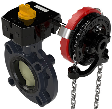
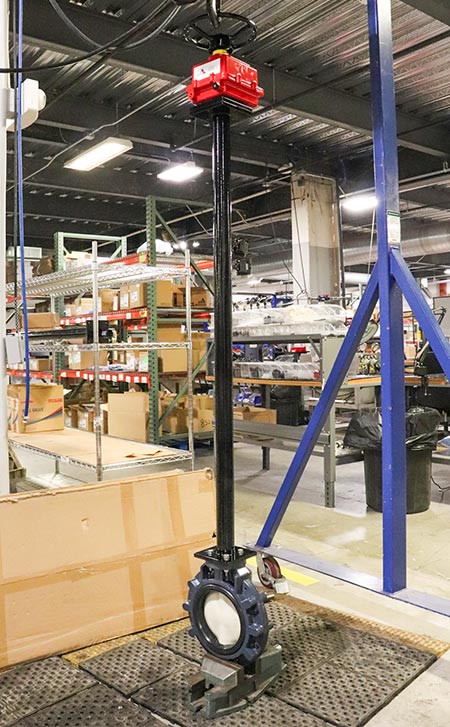
After the proper valve is selected, added accessories and options are available based on the specific requirements of the application. A system designer might ask the following questions: Is the valve below grade, and does it require a stem extension? Is it overhead, and does it require a chain operator? Is it a safety interlock? Should it be automated?
Automation Selection
There are many considerations in automation selection. The first major question a system designer might ask is if the installation requires electric or pneumatic automation. In either selection, a system designer needs to make careful calculations based on the system requirements.
A suitable power source must be available to handle all of the system power requirements. This would include, but not be limited to, a programmable logic controller (PLC), system-wide flow meters/transducers, pH/oxidation reduction potential (ORP) probes, flow meters, level sensors and pumps.
If the system requires pneumatic automation, solenoid valves and compressors must be included in the calculations. Electric actuation would include electrical wiring in the calculations.
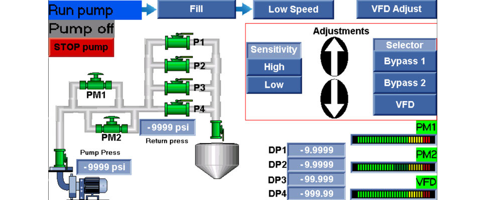
Another consideration would be the use of a SCADA system. This complexity could include a sophisticated setup involving a master PLC overseeing the entire plant, with numerous secondary PLCs managing daily processes. Alternatively, it could be as straightforward as a single PLC operating a compact skid filtration system.
The PLC, otherwise known as the “brain” of the system, receives input from all of the instrumentation, processes it, then sends outputs to the process systems. It recognizes when the pump is running, the flow rate, the pressure, the level of the tanks, the Delta P of the filters and the position the valves are in and commands the valves to open, close or modulate. Previously, this was all accomplished with relay logic, but modern PLCs make this much more user friendly with touchscreen Human-Machine Interfaces (HMIs).
System Operation
The PLC activates the pump, generating system pressure and flow. It needs to ensure the main valve is open to prevent the pump from deadheading against the valve. The SCADA system will check the valve position and open it prior to starting the pump. The flow meters transmit the flow rate to the PLC. The pressure sensors transmit the pressure to the PLC. Valves are in varying states of position, directing the media through the appropriate piping sections. Media runs through the filters, and the Delta P is reported to the PLC. Tanks begin to fill and the tank level is reported to the PLC. If the pressure becomes too high, a pressure relief valve might open and divert some system pressure and flow to bring the pressure back down to the designed operating pressure.
The PLC might also command an automated valve to open, diverting the flow and bringing the system pressure back down to the designed operating range. This could be a modulating valve used to maintain a constant pressure within the system. A modulating valve would react to a 4-20 milliamp (mA) signal or a 3-15 pounds per square inch (psi) signal, depending on if it were electrically or pneumatically actuated. The low number of the signal represents closed, and the high number of the signal represents open. If the valve needs to be 50% open, the PLC would send the appropriate command signal (12 mA for electric or 9 psi for pneumatic), and the valve would react and go to that position. The position is dependent on the designed pressure and the actual pressure. The PLC makes this computation and sends the proper control signal to the valve. Another application for a modulating valve could be to maintain a consistent flow rate. Flow meters would report the media flow rate to the PLC, which would compare that to the desired flow rate setting, then send a signal to open or close the valve to slightly alter the flow.
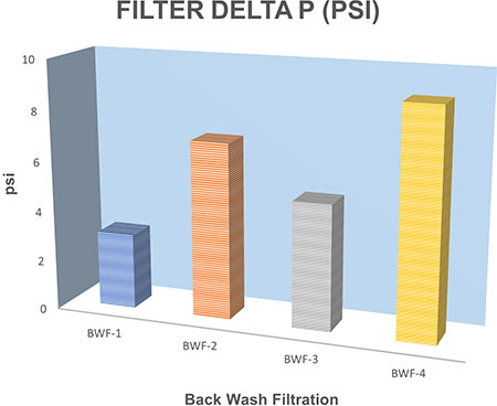
The PLC will consider the Delta P of the filters, and when it gets too high, it will cycle the valves and put the filters into backwash mode. The PLC understands when the filters are clean by the low Delta P, which will command the valves to reverse their cycle and put the filters back online. As the process continues and the tank level rises, the PLC might command the fill valve to close to maintain the proper tank level. Should this valve fail, there would be a high-level dump valve so the tank does not overflow. The PLC would command this valve to open in this case. During the process, the tank level may drop to its low level. The PLC will command the fill valve to open and allow the tank level to rise up to its designed level.
There is always a potential for a full system operation downtime due to a blackout or lack of a power source. In this scenario, failsafe valves drive to their fail open or fail closed positions. It is possible the valve on the discharge side of the pump would close, relieving pressure and diverting the media flow, or the tank valves close, which locks out the tanks. The back-and-forth communication between the PLC and SCADA means the system is working as expected.
While every process valve and piping system is different with variable requirements, this is just a general representation of the various items used within a process system. This article aimed to show some of the intricacies involved in a valve and piping process system. There are manual valves of various types, automated valves of various types, flow meters, pressure sensors, pumps, pH/ORP probes, air compressors, air dryers and pneumatic and electric actuators with different options.