


Soft foot is one of the most prevalent conditions found in rotating machinery. This condition, if not corrected, makes an alignment job much more difficult and sometimes impossible. If the internal alignment is not correct, the external alignment will not matter.
In his book, Shaft Alignment Handbook, noted alignment expert John Piotrowski defines soft foot as the condition "when rotating equipment is set into place on its base, frame or sole plate, one or more than one of the 'feet' are not making good contact at the foot points of the frame." More generally, the condition is caused when there is poor (or no) contact between the feet and the machine base.
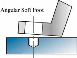
Think of it this way-three points (machine feet in our case) define a plane. When the fourth point, or foot, is shorter than the other three, a soft foot condition exists. In some cases, a measurable rocking of the machine will demonstrate it. This is called gross soft foot. It is easily discernable and correctable with shims. Soft foot that is not as discernable can exist and will cause alignment problems and even cause machine failure if not corrected.
What are the causes of soft foot? The frame can be warped or bent. The baseplate can be warped or bent. The foundation can be uneven or damaged. Machine feet can be bent or broken. A combination of these issues is most likely.
Besides making alignment difficult, there are many reasons why soft foot should be corrected. Tightening down feet where a gap exists (using torque or tension to remove the gap) will cause feet to be bent and sometimes crack. This can also cause the machine case to warp. This condition will put undue stress on the shaft and upset critical clearances in both the driving and the driven machine-bearings, mechanical and shaft seals, pump wear rings, motor armature, stator gaps, etc. Any critical component that comes in contact with the rotation of the shaft can be affected.
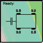
A laser alignment system will record values for you.
Soft foot can cause high levels of vibration. Soft foot can be seen as looseness and exhibit a high 1x vibration signature. In later stages, if left uncorrected, it may show as mechanical looseness as damage to the machine occurs internally. Vibration can cause loosening of feet bolts, and shims can work their way out from under the feet. At this point, the machine can shift drastically. Looseness may eventually present as a high 2x line frequency (7,200 cpm) due to eccentric air gap.
Measuring and Correcting Soft Foot
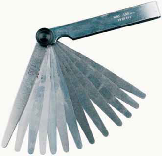
Now that we know that soft foot is bad, we will discuss how to measure and correct it. Even if you have a laser alignment system, it is a good idea to have a couple of dial indicators, a good feeler gauge and a micrometer in your alignment kit. Bring a wire brush for cleaning shims and baseplates. A fine flat file is good for removing burrs on baseplates and machine feet. A good set of precision shims with actual thickness markings for precise stacking tolerances and some good tin snips will be needed to reconfigure shims.
Make sure that shims are clean of all rust and debris, especially if existing shims are reused. The shim should be wide enough to support the entire machine foot. Make sure any dirt and debris is cleaned from under the foot-we always want good metal to metal contact, baseplate to shim to machine foot. Remember, only three to four shims should be under any foot. More shims than that can actually cause a type of soft foot called springy foot. Too many shims will start to act like a spring under the foot, even if the gaps are properly filled.
Before starting, check for gross soft foot. Loosen all of the bolts at the motor feet and check for any obvious rocking of the machine. This needs to be corrected with shims and can be done with a feeler gauge. Make sure to clean the shim packs and only use three to four shims under each foot.
Soft foot can be measured a number of ways. Always start any soft foot measurement with all of the bolts securely tightened. As we go through the different methods, keep in mind that the industry standard for the maximum soft foot measurement is 2 thou (mils) or .25 mm.
Dial indicators are a good method of measuring soft foot. Dials should be anchored to the baseplate or frame and the dial indicators positioned as close as possible to the bolt holes. Make sure the stems are touching the feet and zero set the dial.
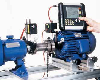
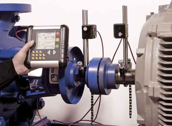
Laser alignment tools include measurement programs for measuring soft foot. Read the instruction manual carefully to follow the proper procedure.
Laser alignment tools include measurement programs for measuring soft foot. Read the instruction manual carefully to follow the proper procedure.
Programs for measuring soft foot.
Now loosen and tighten each bolt, one at a time, in a systematic way to see how much each foot "springs" when it is loosened and all the other bolts are tight. With dial indicators, the best method is to place a dial indicator at each foot and measure the movement on each dial as you loosen and tighten each bolt. This will show the dynamic movement of the entire machine. One dial indicator can be used and moved from foot to foot as you loosen and tighten. Remember, 2 thou (mils) or .25 mm of deflection is within tolerance. Any foot that rises (springs) more than that needs to be shimmed. The movement of the dial stem will record the spring of each foot. Write each movement down as you continue around the machine. This process is similar to the one used with a laser alignment system, but the laser system will record the values automatically.
Now that we have determined our measurements, we have to fix the soft foot. Keep in mind that more than one foot can be soft and each foot needs to be corrected.
Having identified the soft feet, start by removing the existing shim pack from under the foot. Clean the base and the foot of the machine with a wire brush, making sure to remove any corrosion, debris or burrs. Next, use the feeler gauge to measure under each corner of the foot, paying attention for bent or cracked feet. Note the gap at each corner of the foot.
Now fill in those gaps. They may (probably will) be unequal and this is where tin snips are needed. Full shims can be used for the base of the shim pack, but other shims will need to be cut to fill the different gaps under each corner of the feet. Shims can be cut and constructed to form a "stair step" under the foot. Shims can also be cut into L-shapes, partial Us or strips and be used to fill gaps accordingly.
Use the measurements from the feeler gauge to build the shim pack. Use the micrometer to measure the thickness of the shim pack as most shims have a tolerance factor. Do not use more than three to four shims under any foot.
Use the feeler gauge to measure under each corner of the foot, paying attention for bent or cracked feet.
Once the gaps are filled, retighten all of the hold down bolts. Use a diagonal pattern to tighten, from one corner to its diagonal opposite. Hand tighten at first, then work your way around the machine in the same pattern, tightening each bolt a little more each time. Once the bolts are tight, re-measure-loosening and tightening each bolt one at a time. Make sure that no foot has a deflection of more than 2 thou (mils) or .25 mm.
A good set of precision shims with actual thickness markings for precise stacking tolerances and some good tin snips will be needed to reconfigure shims.
When you are confident soft foot is eliminated, re-tighten the bolts in the same pattern. Now you are ready to start your shaft alignment measurement.
A lot of work can go into proper soft foot correction, but it is worth it. Even though the shaft center lines are aligned, it does not mean that things are aligned internally once everything is torqued down to specification. Remember, the goal is to always make rotating equipment last as long as possible. Do it right the first time and you will not have to do it again.
Pumps & Systems, May 2010
For more information on soft foot and shaft alignment, see John Piotrowski's book, the Shaft Alignment Handbook, Third Edition.