


- Can we make it until. . . ?
- When should I plan for a major overhaul?
- Is this compressor safe to run?
- Should we go into the compressor during this outage, or can we make it until the next one?
Deciding whether to repair a machine or keep it running can be a time of high anxiety, especially if limited information is available to make a decision. Fortunately, the right tools and training can now give you the ability to "see" inside your reciprocating compressors to make confident decisions on repairs.
Reciprocating compressors are unique in that they are the only compressor type I know whose thermodynamic cycle can be accurately analyzed in great detail using commercially available analysis equipment. Advances in portable reciprocating compression analyzers have made them capable of collecting, storing and analyzing actual P-V plots. P-V plots are pressure-volume diagrams that are generated by measuring dynamic pressure data inside compressor cylinders and plotting them against the displaced volume of the cylinder. The displaced volume is calculated by correlating the crank angle to the position of the piston and multiplying this value by the piston area.
P-V plots, when evaluated along with vibration data, are immensely valuable in assessing performance and detecting internal malfunctions. "Reciprocating Compressor Basics" is a useful overview of reciprocating compressor technology that includes a clear explanation of the thermodynamic cycle and what a typical P-V diagram looks like. Anyone who works with or around reciprocating compressors should read this article.
As some of the most critical and expensive systems at a production facility, reciprocating compressors deserve special attention. Gas transmission pipelines, petrochemical plants, refineries and many other industries all depend on this type of equipment. Due to many factors, including but not limited to the quality of the initial specification/design, adequacy of maintenance practices and operational factors, industrial facilities can expect widely varying life cycle costs and reliability from their own installations.
Various compressors are found in almost every industrial facility. Types of gases compressed include:
- Air for compressed tool and instrument air systems
- Hydrogen, oxygen, etc. for chemical processing
- Light hydrocarbon fractions in refining
- Various gases for storage or transmission
- Other applications
There are two primary classifications of industrial compressors: intermittent flow (positive displacement), including reciprocating and rotary types; and continuous flow, including centrifugal and axial flow types.
Reciprocating compressors are typically used where high compression ratios (ratio of discharge to suction pressures) are required per stage without high flow rates, and the process fluid is relatively dry. Wet gas compressors tend to be centrifugal types. High flow, low compression ratio applications are best served by axial flow compressors. Rotary types are primarily specified in compressed air applications, though other types of compressors are also found in air service.
Basic Design of a Reciprocating Compressor
The primary components of a typical reciprocating compressor system can be seen in Figures 1 and 2. Note that the author has never seen a "typical" compressor installation, and acknowledges the existence of many exceptions.
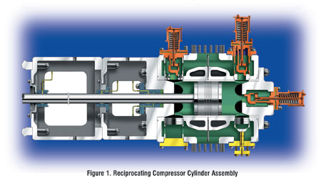 A particular design may have from one to six or more compression cylinders (Figure 1), also known as stages, which provide confinement for the process gas during compression. A piston is driven in a reciprocating action to compress the gas. Arrangements may be of single- or dual-acting design. (In the dual-acting design, compression occurs on both sides of the piston during both the advancing and retreating strokes.)
Some dual-acting cylinders in high-pressure applications will have a piston rod on both sides of the piston to provide equal surface area and balance loads. Tandem cylinder arrangements help minimize dynamic loads by locating cylinders in pairs, connected to a common crankshaft, so that the movements of the pistons oppose each other.
Gas pressure is sealed and wear of expensive components is minimized with disposable piston rings and rider bands respectively. These are formed from comparatively soft metals relative to piston and cylinder/liner metallurgy or materials such as polytetrafluoroethylene (PTFE).
Most equipment designs incorporate block-type, force-feed lubrication systems; however, when there is zero process tolerance for oil carryover, nonlubricated designs are employed. Cylinders for larger applications (typical cutoff is 300-hp) are equipped with coolant passages for thermosyphon or circulating liquid coolant-type systems, whereas some smaller home and shop compressors are typically air-cooled. Large application cylinders are generally fitted with replaceable liners that are press-fitted into the bore, and may include an antirotation pin.
Process gas is drawn into the cylinder, squeezed, contained and then released by mechanical valves that typically operate automatically by differential pressures. Depending on system design, cylinders may have one or multiple suction and discharge valves. Unloaders and clearance pockets are special valves that control the percent of full load carried by the compressor at a given rotational speed of its driver. Unloaders manipulate the suction valves' action to allow the gas to recycle. Clearance pocket valves alter the cylinder head space (clearance volume). They may be fixed or variable volume. These devices are beyond the scope of this article.
The distance piece (sometimes called doghouse) is a structural member connecting the compressor frame to the cylinder. Intermixing of fluids between the cylinder and the distance piece must be avoided. Packing rings contain gas pressure within the cylinder, and they keep oil from entering the cylinder by wiping oil from the piston rod along its travel. The distance piece is typically vented according to the most hazardous material in the system, which is often the gas compressed in the cylinder. The packing rings are designed to contain the gas within the cylinder, but with the high pressure it is possible that some of the compressed gas will leak past the packing rings.
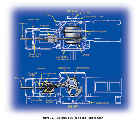 The running gear, housed within the compressor frame (Figure 2), consists of the crosshead and connecting rod, which connect the piston rod to the crankshaft, converting its rotary motion into a reciprocating linear motion. The crankshaft is fitted with counterweights to balance dynamic forces created by the movement of the heavy pistons. It is supported within the frame of the compressor by plain bearings at several journals. A flywheel is also provided to store rotational inertia and provide mechanical advantage for manual rotation of the assembly.
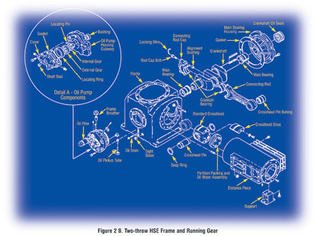 Some compressors will lubricate their frame running gear with an integral, shaft-driven oil pump, while others are provided with more extensive, skid-mounted lubrication systems. All properly designed systems will provide not only for oil circulation to the critical tribo-surfaces of the equipment, but also for lubricant temperature control, filtration and some measure of instrumentation and redundancy.
Suction gases are generally passed through suction strainers and separators to remove entrained particulates, moisture and liquid phase process fluid that could cause severe damage to the compressor valves and other critical components, and even threaten cylinder integrity with disastrous consequences. Gas may also be preheated to coax liquid process gas into the vapor phase.
Intercoolers provide an opportunity for heat removal from the process gas between compression stages (see the next section). These heat exchangers may be part of the compressor's oil and/or cylinder cooling system(s), or they may be connected to the plant's cooling water system. On the discharge side, pressure vessels serve as pulsation dampeners, providing system capacitance to equalize the flow and pressure pulsations corresponding to the piston's compression strokes.
Typically, reciprocating compressors are relatively low-speed devices, and are direct- or belt-driven by an electric motor, either with or without a variable speed drive controller. Often the motor is manufactured to be integral to the compressor, and the motor shaft and compressor crankshaft are one-piece, eliminating the need for a coupling. Gearbox-type speed reducers are used in various installations. Sometimes, though less commonly, they are driven by steam turbines or other sources of power such as natural gas or diesel engines. The overall design of the system and the type of driver selected will influence lubrication of these peripheral systems.
The Thermodynamic Cycle
An explanation of a few basic thermodynamic principles is necessary to understand the science of reciprocating compressors. Compression occurs within the cylinder as a four-part cycle that occurs with each advance and retreat of the piston (two strokes per cycle). The four parts of the cycle are compression, discharge, expansion and intake. They are shown graphically with pressure versus volume plotted in a P-V diagram (Figure 3).
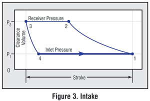 At the conclusion of a prior cycle, the piston is fully retreated within the cylinder at V1, the volume of which is filled with process gas at suction conditions (pressure, P1 and temperature, T1), and the suction and discharge valves are all closed. This is represented by point 1 (zero) in the P-V diagram. As the piston advances, the volume within the cylinder is reduced. This causes the pressure and temperature of the gas to rise until the pressure within the cylinder reaches the pressure of the discharge header. At this time, the discharge valves begin to open, noted on the diagram by Point 2.
With the discharge valves opening, pressure remains fixed at P2 for the remainder of the advancing stroke as volume continues to decrease for the discharge portion of the cycle. The piston comes to a momentary stop at V2 before reversing direction. Note that some minimal volume remains, known as the clearance volume. It is the space remaining within the cylinder when the piston is at the most advanced position in its travel. Some minimum clearance volume is necessary to prevent piston/head contact, and the manipulation of this volume is a major compressor performance parameter. The cycle is now at Point 3.
Expansion occurs next as the small volume of gas in the clearance pocket is expanded to slightly below suction pressure, facilitated by the closing of the discharge valves and the retreat of the piston. This is Point 4.
When P1 is reached, the intake valves open, allowing fresh charge to enter the cylinder for the intake and last stage of the cycle. Once again, pressure is held constant as the volume is changed. This marks the return to Point 1.
Comprehending this cycle is essential to diagnosing compressor problems and understanding compressor efficiency, power requirements, valve operation, etc. This knowledge can be gained by trending process information and monitoring the effect these items have on the cycle.
All artwork from Reciprocating Compressor Training, Dresser-Rand. Reprinted with permission.
Pumps & Systems, December 2008