


Today's lean maintenance staff needs pump and motor protective devices that diagnose and predict problems before they become acute.
Pumps are indispensable in mining, petroleum recovery (wellhead operations), pipelines, refining and many manufacturing operations, so their failure causes costly unscheduled downtime. In the case of an electrical ground fault the pump's drive motor can be destroyed, and it can result in high voltage potential on the pump equipment framework that is a serious safety hazard to personnel. A pump and drive motor can fail in other ways, including pumps running dry and jammed pumps causing the motor to overload, which can lead to catastrophic damage to the motor and other electrical system problems.
Automated Prevention
Most fault conditions can be mitigated with the right kind of protective device. Today's electronic motor protection relays (Figure 1) can communicate motor operating information to a programmable logic controller (PLC), motor control center or an automated monitoring system. These real-time diagnostic features are important predictive/preventative maintenance functions that indicate that a problem needs attention before a catastrophic failure.
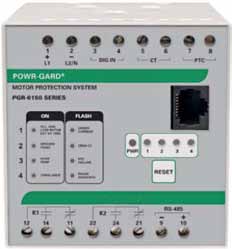
Figure 1. Electronic pump/motor protection relay
Some motor protection relays have inputs for temperature sensors. Temperature inputs in some relays shut down the motor before it becomes too hot and causes an insulation failure. More importantly, collecting temperature data from the ambient surroundings, pump and motor bearings and the motor windings can be used for predictive/preventative maintenance.
By monitoring and analyzing motor thermal trends, operators can see that the motor may become overheated if operating conditions are not altered. Overloading the motor, ambient temperature and lack of cooling when needed may overheat the motor. With temperature sensor inputs, the relay's thermal model of the motor can be biased to reflect operating conditions or adjust for hot spots on the motor, such as windings or bearings. These diagnostic features provide more efficient troubleshooting and help avoid motor damage, freeing up staff and eliminating many repairs and replacements. Instead of reacting to failures, maintenance staff can proactively schedule corrections.
Drive Motor Ground Faults
Pumps are often used in dusty and damp environments that can compromise insulation in the drive motor and its input wiring. These conditions can increase “earth leakage” currents—persistent, small currents from a high potential point to ground that may be a precursor to a major ground fault. Some causes of phase-to-ground faults are shorts in the motor windings or input wiring due to worn or melted insulation. Ground faults can cause electrical shocks, fires or even major arc-flash events.
Thermal Overload Relays
Earlier methods of detection and protection against ground faults are still being used. These electromechanical devices include bimetallic or melted alloy (eutectic) overload mechanisms. They contain heating elements wired in series with the motor inputs that cause either a pool of solder (eutectic alloy) to melt or a set of bimetallic strips to bend and release the contacts when current becomes excessive.
Bimetallic overloads generally have a limited range of adjustable trip points. No adjustability is possible with eutectic alloy mechanisms. Some bimetallic overloads will reclose automatically when the motor cools sufficiently. Bimetallic overload design can include compensation to prevent ambient temperature changes from affecting the trip point. Ideally, a thermal overload should be installed in the same ambient temperature as the motor it protects. In practice, these devices are often installed in the motor starter, which may be in an air-conditioned switchgear room away from the motor. What's more, their simple design precludes intelligent feedback.
Solid-State Electronic Protection
Certain types of solid-state overload relays have been introduced to resolve the inaccuracies of electromechanical devices. However, many of these have pre-calculated setpoints and cannot provide the same level of protection as more recent designs. In one type, the current is measured using a set of current transformers, which may be internal or external to the device. This protection system includes monitoring and current interruption in case of ground faults, overloads, unbalance, jams, etc.
However, using a current transformer may allow some level of damage to occur before the relay trips. An alternative to current monitoring is to use an insulation monitoring relay. This device monitors phase-to-ground insulation resistance and prevents the motor from starting if system insulation resistance falls below a selected set-point, avoiding potential motor damage.
An insulation monitoring relay applies a DC voltage and measures the leakage current to determine the system's insulation resistance to ground. By establishing a setpoint for this resistance and providing a signal output when it is too low, maintenance staff is made aware of degradation, allowing for scheduled maintenance and repair.
Another benefit, compared to electromechanical relays that pass motor current through heating elements, electronic relays do not cause excessive heat buildup on a power panel. Besides saving on power consumption, this helps avoid panel de-rating and the use a larger enclosure for heat dissipation.
Yet another type of electronic device combines ground fault protection with a ground-check function, which monitors the integrity of an equipment ground. It is used if ensuring ground continuity is the foremost issue. These relays are also used with trailing cables, when the equipment may be a large distance from the starter or breaker.
By ensuring a ground connection, this prevents a potential voltage rise across the fluid or on the framework of the equipment during a ground-fault, which may represent a shock hazard to operating and maintenance personnel. Common application environments are surface mines, underground mines, quarries and submersible pumps. These devices are even used on the pumping equipment for golf course watering systems. They can also be used as a remote permissive for the pumping equipment.
In many electrical systems, a neutral grounding resistor (NGR) is used on the grounding system. This is sometimes called a high resistance ground (HRG), where a resistor is placed between the neutral of the supply transformer and ground.
Using resistance grounding can minimize the amount of damage caused by a ground fault. In some cases, it may allow operations to continue until the fault can be cleared. In addition, an NGR used in conjunction with an NGR monitor relay can provide a predictive maintenance function by alerting staff to the ground-fault before excessive damage is done. Moreover, resistance grounding also prevents a re-striking fault from elevating the system voltage relative to ground, which adds more stress to the insulation and can lead to a phase-to-ground-to-phase fault.
Pump manufacturers are being asked to incorporate ground-check relays into their equipment. This includes a zener diode termination assembly that is part of the relay's open and shorted ground-check loop functions for portable power cables. The relay feeds two different levels of current to the termination assembly and checks to make sure that the voltage drop is the same across the zener diode at both levels. This is a more desirable way of ensuring ground integrity compared to a resistance terminated loop, as a high-impedance fault with the right amount of resistance can provide an erroneous indication.
Benefits of Microprocessor-Based Protection
Microprocessor-based relays may incorporate several of these protective and predictive functions to guard pumps and motors from overload damage and some other fault conditions. Depending on the design and feature-set, they may include a limited functions or a wide range of protection and monitoring features. Some of the advanced features include protection in the event of phase loss, phase imbalance, improper phase sequence, jam and undercurrent protection. Other features may include digital inputs/outputs, internal data logging, and interfacing data communications. See Figure 2.
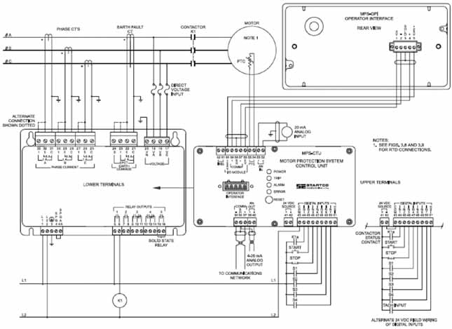
Figure 2. Microprocessor-based motor protection relay simplified circuit diagram
A useful feature for maintenance personnel is continuous real-time monitoring of an operating motor's thermal capacity. As mentioned earlier, this may prevent a motor from becoming overloaded, avoiding insulation damage.
Combined with a data communications interface, this monitoring allows trend analysis by a central control system computer or PLC and subsequent scheduled maintenance.
A pump jam will cause motor overload due to excessive current that can damage the motor windings' insulation. A motor protection relay will interrupt the supply power as it does for a ground fault. A pump running dry does not cause an overcurrent condition but a low current—a common occurrence in submersible pump applications. Mechanical floats may not be sufficient, as they may be prone to failure. In many cases, a pump that runs dry means a loss of lubrication, which can lead to bearing damage or other failure modes.
A microprocessor-based relay with a low-current setpoint can protect against a dry pump situation. During normal operation the microprocessor sees nominal operating amperage.
If the pump runs dry, this current drops to an “idle” amperage level, which is defined by the motor. When that occurs, the protective relay can send a signal to an interrupt device, or signal to a PLC for analysis, which may actuate the interrupting device.
Cost Considerations
Microprocessor-based motor protection devices can be sophisticated. In addition to current inputs, some devices have provisions for voltage inputs, which can calculate power, power factor and other parameters. These parameters are fed back to a motor control center or PLC where the data can be logged and/or analyzed.
Network communication capabilities may include protocols for Ethernet, DeviceNet or ProfiBus. With these, microprocessor-based motor protection can be used to help optimize a pump/motor system electrically and mechanically. Some decisions and actions that may be taken are load analysis, altering flow rate or changing power factor correction.
The cost of devices with this level of sophistication may be prohibitive for pumping systems operating with 50-horsepower or smaller motors. In these cases, simpler microprocessor-based devices may be a cost-effective way to upgrade an antiquated pumping system or add protection to a system.
Another consideration is the measurement devices required for use with the protection relays. For example, some microprocessor-based relays have built-in current transformers (CTs) for overcurrent detection circuitry with specified current ranges. In other cases, these CTs must be purchased and installed. In some cases, using separate CTs may be appropriate, allowing a protection relay to be tied into almost any power system.
Of course, reliability in harsh industrial environments has a significant impact on the overall cost of ownership when a pump/motor protective device is purchased. Besides exposure to water and electrically conductive dusts, corrosive liquids and vapors are common in many applications. For example, hydrogen sulfide (H2S) can be present in or around petrochemical fluids, which affects equipment used at the wellhead, on pipelines and in refineries. It reacts with water vapor to form sulfuric acid that eats away at electrical components.
For these and other harsh environments, protective devices designed specifically to survive in such applications should be chosen. In addition to rugged mechanical design for use on machinery with strong vibrations, the electrical circuit boards need to be conformal coated with an insulating material. When done properly, this seals the components and circuit traces so they cannot be attacked by corrosive liquids, vapors and gases.
A unit designed primarily for indoor factory applications may last only a short time in a mining or petrochemical application. However, protective devices designed for rugged environments can supply 20 or more years of reliable service in such environments. A long service life may be a compelling reason to purchase a reliable protective device, even for less demanding applications, because of its low cost of ownership.
Summary
Microprocessor-based pump/motor protection relays offer a cost-effective way to prevent catastrophic failures due to a number of fault conditions. In addition, they can protect operating and maintenance personnel by mitigating or removing shock hazards and potential arc-flash events. Those with real-time monitoring and diagnostic functions for predictive/preventative maintenance programs can reduce maintenance costs.
Pumps & Systems, November 2011