


Last year in “Trending Revelations in Vibration Analysis,” (Pumps & Systems, June 2009), I discussed the importance of statistic trending in vibrations analysis. Usually, as most would expect, vibrations gradually increase with time. This increase reflects the normal internal wear, accumulative misalignment and deformations that can occur within a pump. All these wear conditions will lead to eventual failure.
The slope of the statistical vibration curve often begins an exponential increase just before an actual failure occurs. If monitored and detected in time, a failure can be prevented, avoiding run interruptions and the costs of a catastrophic situation.
However, what if the trending revealed an alternating pattern, showing high vibrations one day and low the next? Obviously, some process variation(s) would be suspected, but these variations are not always easily pinpointed.
Installation of Online Monitoring Systems
For most critical, large, expensive machines, an online monitoring system should be installed, such as proximity probes for main boiler feed pumps at power stations. Such monitoring systems are designed to send an alarm to shut down a critical unit, which can prevent catastrophic failure.
Such instrumented units are rarely used due to their expense and are only installed on the most critical machinery. The majority of the remaining equipment (more than 90 percent of many plants' pump populations) remains either unmonitored or monitored occasionally, perhaps during periodic monthly inspections. Failure of these “semi-critical” units is therefore left to chance.
If such an unexpected failure occurs between hand-held vibration monitoring routes, it can cause a considerable problem to the plant. A simple, yet inexpensive and portable monitoring method could fill the gap between either choosing an expensive permanent system or having no system at all.
Case Study
Consider a multistage centrifugal pump (discussed in “Pumping Prescriptions,” Pumps & Systems, October 2010). This pump was installed at a pipeline and experienced random vibration fluctuations, as displayed through the use of the monthly route data from Specific Comprehensive Operation of Plant Equipment (SCOPE), as shown in Figure 1. In this application, two pumps operate either each at a given time or both running in parallel, depending on the flow production (transfer) demand.
Figure 1. Monthly vibration route reveals unpredictable swings—taken from Specific Comprehensive Operation of Plant Equipment (SCOPE). (SCOPE system: www.pumpingmachinery.com/consulting/SCOPE/scope.htm)
To determine the root cause of such swings, a fault-predict system was installed to track the system's vibrations. The objective was to find a system that would be simple and transportable (find the root cause and move on) and with the ability to measure pressures and temperatures in addition to vibrations.
The system also needed to be inexpensive and wireless, for simple installation. Flexibility of use and ease of training for engineers and maintenance professionals was also a requirement. The end user also wanted the system installed and operational in one day.
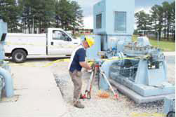
Figure 2. A fault-predict system being installed.
The Root Cause
The results of this troubleshooting project revealed a trend after gathering information for approximately one week, pinpointing a possible root.

Figure 3. A fault-predict system shows traces of vibrations and pressures over time and when different products are pumped.
Below is an explanation of the root cause of the vibration, which is illustrated in of Figure 3:
Zone A—Pump 1 is off. Its discharge pressure (P1) is the same as its suction pressure (approximately 80 psig). Pump 2's discharge pressure is approximately 850 psi, i.e. Pump 2 develops approximately 850 - 80 = 770 psi differential pressure. The product pumped is gasoline. Vibrations of Pump 2 are low, below 0.20 inch per second.
Zone B—Pump 1 kicks in. Its discharge pressure rises to approximately 400 psi, and Pumps 1 and 2 together produce a discharge pressure at the exit of Pump 2 of approximately 1100 psig. Vibrations remain low.
Zone C—A new product (diesel oil) begins to flow thru the pipeline, with Pumps 1 and 2 continuing to operate. Vibration increases to over 0.8 inch per second—a significant increase, exceeding the alarm.
Zone D—Pump #1 goes down for a brief inspection. Pump 2's pressure drops, reflecting its single operation, but vibrations do not change and remain high.
Zone E—Pump 1 comes back on-line. Vibrations do not change, remaining high, typical for diesel oil regime.
Zone F—Pipeline transitions back to gasoline.
Zone G—Back to gasoline, with a single pump (#2) in operation—vibrations immediately drop, reflecting gasoline transfer.
Zone H—Pumps are off for inspection
Zone I—Operation resumes with Pump 2 on; vibrations are low, characteristic of gasoline operation.
The review of the fault-predict system result trend revealed a strong relationship between the vibrations and the product being pumped. Diesel fuel and gasoline were these products. The viscosity and density (specific gravity) of these products (Figure 4) are different, so much so that they caused a change in the rotor-dynamic behavior of the rotor.
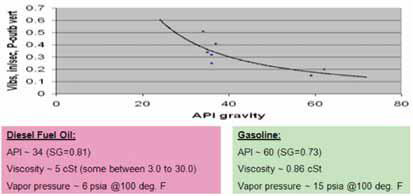
Figure 4. The different fluid characteristics of diesel fuel and gasoline affect the internal damping and stiffness of the multistage rotor.
Why the Change?
The explanation of such drastic behavior of the rotor is due to the Lomakin effect1. Modifications to the rotor to eliminate the response are relatively straightforward, but the initial detection was not so clear during operation, when a variety of other concerns and priorities are occurring at a plant.
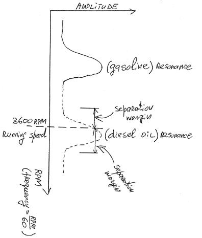
Figure 5. The critical speed of the rotor “shifts” depending on the properties of the pumped fluid. The shift may result in tune-in (or tune-out, depending on the characteristics of the machine and fluid pumped) of the response into (or close to) running speed
Conclusion
This type of troubleshooting presents a good way of quickly finding the problem, with corrective action(s) applied as necessary, without the major capital expense of a permanent system. A portable system avoids significant expense and achieves the objective of solving a problem and learning from the experience.
Pump world enthusiasts can review the system's on-line operation at the sample site www.pumpingmachinery.com/consulting/SCOPE/scope.htm; (username = pmdemo and password = pmdemo1).
References
1. Stepanoff, A.J., Centrifugal and Axial Flow Pumps, Wiley Publications, 2nd Edition, 1957.
Pumps & Systems, November 2010