


Jerry, my repair shop manager, called me for advice on a recent problem he had with an end-suction, vertically-mounted, raw sewage intake pump. He was troubleshooting the problem at a lift station of a major municipal water treatment plant.
The Problem
“Lev, the bearings are running hot, and the plant maintenance guys are concerned,” Jerry tells me. “They say they follow the IOM procedures by the book, but the temperature is going above 200 degrees F, and the pump shuts down at these temperatures. They wonder if my guys should pull the pump and inspect it at our shop, but I would first like to do some checking in the field to see if we can find something obvious.”
“Can you send me some photos of the installation and a sectional drawing?” I ask. “Also, tell me more about this problem. Is the pump running continuously, or with leads/lags?”
I asked this question because influent lift station pumps typically run in sequence. The first pump may run for 20 to 30 minutes drawing down the wet well then shuts off and station idles until the well builds up. Then the second pump takes the lead, runs and shuts off, and then the third, and so on. In this mode, a pump would hardly get its bearings higher than 130 to 150 degrees F for the short time it operates.
“No problem. I'll email the photos to you right away,” Jerry says. “B but call me back as soon as possible. I am running out of ideas, and the grease plugs at this housing do not look right.”
Jerry was timing the pumps between runs and measuring the temperature climb. The 200 degrees F, after 20 minutes of run time, did not sound right to him, nor to me. Something was wrong.
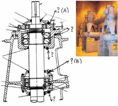
Figure 1. (right) End-suction, vertically-mounted, raw sewage intake pump
Figure 2. (left) Drawing of the pump
After examining the images (Figures 1 & 2) that he emailed me, I called him back. “The lower housing seems to have a double-row, radial load bearing. The upper housing has two bearings: a tandem arrangement, 40-degree angular contact to take the main thrust, and a bumper single row bearing to take a start-up, transient up-thrust. I am confused about the greasing arrangement. The lower housing has a grease fitting (B) on the top, and a pop-up relief plug at the bottom. The top housing has two grease injection fittings (one at the top chamber and another between the bearings) and a pop-up relief plug at the bottom. Is that right?”
“That's right,” Jerry says. “That is what's bothering me. How do they make sure the bearings are not over-greased? The relief plugs are supposed to pop open and relieve the pressure if the chambers are full of grease. However, as soon as the pressure relieves, the pop-up relief closes, and the chambers remain mostly filled. This would make the bearings run hot. I also see clear signs of that because the whole housing is a mess—mostly at the top, but it's OK at the bottom.”
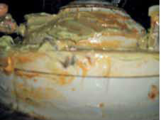
Figure 3. Excess grease on the housing
“They say the IOM procedure manual tells them to pump two strokes of the grease gun,” Jerry continues. “They showed me where they inject the grease: into A at the top housing and B at the bottom. They do this monthly per work order request. They have been doing it for about seven months, since the pump was installed.”
Two strokes are barely a fraction of an ounce. Through seven months, the number of strokes would be 14, which would perhaps be an ounce or two, not enough to even be close to over-greasing. This assumes that they did what they said and did not add a few more strokes just to be safe.
“What else do you see?” I ask. “Is the pump pumping OK? Is it vibrating?”
“It pumps fine. The operators are happy, and vibrations are low. I just took measurements myself. The issue is that the housing definitely looks over-greased, but only at the top side of the housing.”
Jerry pauses thinking, “It would make sense according to the fittings. Grease cannot be injected into the bottom portion of the upper or lower housings, other than relying on the dripping of grease through the entire row of bearings.”
“You've said enough.” I say, now worried too. “Pull the pump and get it to the shop. I will see you there when the pump is opened.”
The Answer
Grease arrangements are many.1 Sealed-for-life, open, shield-on-one-side, dead-headed arrangement, thru-flow arrangement and cross-lubrication are some of the numerous techniques used. Improper lubrication—too much, or not enough, grease—could mean trouble.2
In practice, perfection is almost impossible.3 Bearings are initially greased at the OEM manufacturer or after repairs. The amount of grease is usually 50 percent (half the space within the bearing is filled), plus some grease is added within the chamber itself. That is all that the bearings actually need, and they will run cool, about 100 to 130 degrees F, or 10 to 20 degrees F higher for a roller bearings case. Going over 150 degrees F, approaching 180 degrees F and certainly going beyond 200 degrees F is a sign of too much grease or other bearing-related issues.
The real challenge is not when the bearings are greased at the shop, but rather when they are re-greased in the field. Not knowing what is inside, how much grease should a mechanic add? Manuals vary on recommendations, but the simplest, and perhaps most reliable, is to inject new grease until the old grease is purged and is followed by the new fresh grease coming from the relief port (which must be open completely).3
The pump may or may not have pop-up plugs. If it does have them, they should serve as a precautionary measure, and the relief plugs should also be present. Sometimes, if relief plugs are not present, the pop-ups should be entirely removed during re-greasing, and the pump allowed to run for 15 to 30 minutes, while watching the fresh grease leak out, being pumped out by the bearings.
After that time, the plugs would be put back in to keep the remaining grease inside. Such procedure would result with roughly 50 to 70 percent of the grease left inside the housings, without the bearings being over-packed with grease, and therefore running cool.
Jerry's next action was to modify the housings, to make sure each chamber had its own way in (grease fitting) and its own way out (pop-up plugs). The pop-up, plugs would need to be removed at each re-greasing. After 15 to 30 minutes of pump running, replaced.
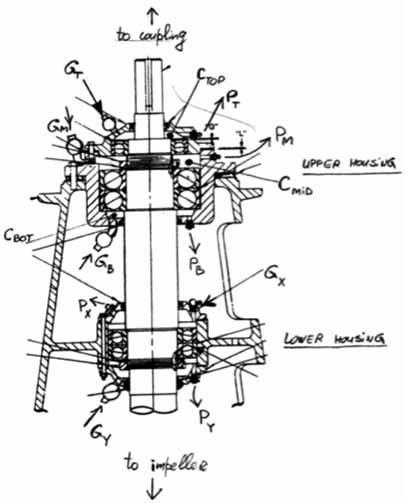
Figure 4. The pump with injection ports labeled
Ctop, Cmid and Cbot are cavities on top of the top bearing at the upper bearing housing. Gt, Gm and Gb are injection ports (grease fittings), and Pt, Pm and Pb are pop-up relief plugs (also served as relief plugs to be opened during relub). Similar designations are shown for the lower housing (G = grease in, and P = pop-ups). The logic made too much sense, and the plant maintenance did not buy it. Why waste so much grease every month? “Is there a simple method?” they had asked Jerry. There is indeed. Perhaps not perfect, but a compromise.
That is how the final procedure was modified.. Can you guess how? The person with the winning answer gets a free ticket to our Pump School session: www.pumpingmachinery.com/pump_school/pump_school.htm. The solution will be included in the January 2011 issue of Pumps & Systems.
References
1. Nelik, L., “To Grease or Not to Grease,” Pumps & Systems, August 2005.
2. SCOPETM Reliability Program, www.pumpingmachinery.com/pump_magazine/pump_articles/articles_summary.htm (Article #33).
3. Nelik, L., “Reliability of Grease Lubrication Methods,” www.pumpingmachinery.com/pump_magazine/pump_articles/article_07/article_07.htm