


|
Q. When measuring vibration on vertical pumps, does the allowable vibration depend on the height of the motor or on the height above the baseplate where the readings are taken? A. The allowable vibration levels published by ANSI/HI Standard 9.6.4, Centrifugal and Vertical Pumps for Vibration Measurements and Allowable Values, are for one location only-usually near the upper motor bearing of vertical pumps with close-coupled motors or at the junction of the pump discharge head and the bottom mounting face of the motor. To determine the correct location of the vibration probes, consult the standard. The probability of vibration damaging any pump is dependent upon two factors: 1) The stress placed on any components within the pump or any component, such as a gearbox or motor, which is mounted on the top of the pump and 2) the likelihood of interference at close running clearances inside the pump or driver. The scale of all components, including their close-running clearances, generally increases with the size of the equipment. Therefore, in larger pumps and motors, higher vibration displacement levels would be expected before undue deterioration occurs. However, larger equipment typically runs at slower speeds. A user can approximately and simultaneously account for the increasing size and reducing speed of the equipment by using specifications based on vibration velocity, rather than vibration displacement. Worldwide specifications, including ANSI/HI as well as ISO, use vibration velocity as the preferred method of vibration measurement in pumps and their driving equipment. When vibration velocity is used as the measurement parameter, the size of the equipment-including height above the baseplate-is of less significance. However, we recognize that actual vibration levels on vertical pumps will increase as the distance from the baseplate increases. Even this statement depends upon the assumption that the excited vibration mode is the "first reed bending" frequency (the top and bottom of the motor bend in the same direction). The best approach is to use the general specifications only at the measurement points to which they apply, and to seek the advice of the manufacturer concerning the proper interpretation of vibration readings taken at any other locations.
|
|
Q. When measuring vibration on vertical pumps, does the allowable vibration depend on the height of the motor or on the height above the baseplate where the readings are taken? A. The allowable vibration levels published by ANSI/HI Standard 9.6.4, Centrifugal and Vertical Pumps for Vibration Measurements and Allowable Values, are for one location only-usually near the upper motor bearing of vertical pumps with close-coupled motors or at the junction of the pump discharge head and the bottom mounting face of the motor. To determine the correct location of the vibration probes, consult the standard. The probability of vibration damaging any pump is dependent upon two factors: 1) The stress placed on any components within the pump or any component, such as a gearbox or motor, which is mounted on the top of the pump and 2) the likelihood of interference at close running clearances inside the pump or driver. The scale of all components, including their close-running clearances, generally increases with the size of the equipment. Therefore, in larger pumps and motors, higher vibration displacement levels would be expected before undue deterioration occurs. However, larger equipment typically runs at slower speeds. A user can approximately and simultaneously account for the increasing size and reducing speed of the equipment by using specifications based on vibration velocity, rather than vibration displacement. Worldwide specifications, including ANSI/HI as well as ISO, use vibration velocity as the preferred method of vibration measurement in pumps and their driving equipment. When vibration velocity is used as the measurement parameter, the size of the equipment-including height above the baseplate-is of less significance. However, we recognize that actual vibration levels on vertical pumps will increase as the distance from the baseplate increases. Even this statement depends upon the assumption that the excited vibration mode is the "first reed bending" frequency (the top and bottom of the motor bend in the same direction). The best approach is to use the general specifications only at the measurement points to which they apply, and to seek the advice of the manufacturer concerning the proper interpretation of vibration readings taken at any other locations. |
|
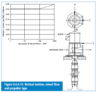
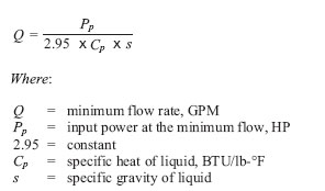
See Figure 9.6.4.13 for allowable vibration levels for Vertical Turbine Pumps. The values in ANSI/HI 9.6.4 are not applicable to factory or laboratory acceptance tests. Experience has shown that vibration levels measured on temporary factory setups may be as much as two times higher than those obtained in the field. It must be recognized that the field vibration acceptance levels are applicable to the pump when operating anywhere within the preferred operating range. Q. I know that a centrifugal pump can overheat badly if run at shut-off too long, but how can I determine the minimum rate of flow through the pump to avoid excess temperature build up? A. Commonly accepted practice limits temperature rise through a pump to 15-deg F. For most installations, this is adequate, and minimum flow may be calculated with this equation:
|
|
At the minimum flows calculated using the above equation, the power input is approximately the same as at shut-off. Catastrophic failure of the pump and associated equipment may result if the liquid within the pump casing is allowed to vaporize. To prevent flashing, a flow must be maintained through the pump that will keep the liquid below its saturation temperature. Minimum flow is guaranteed by installing a bypass from the discharge line to some low-pressure point in the system. The bypass should not lead directly back to the pump suction. An orifice installed in the bypass line breaks down the differential pressure between the pump discharge and the low-pressure point in the system. The bypass may be manually or automatically operated, but must be open during periods of light load or when starting or stopping the pump. This subject is discussed in greater detail in ANSI/HI 1.3 Centrifugal Pumps for Design and Application. Q. What is a pitot tube pump? |
|
A. The pitot pump, a variation of the rotodynamic pump design, uses a closed casing that is attached to and rotates with the impeller (cover) while a stationary pitot tube captures the discharge flow (Figure B1.3.2.1.2.3a). The inlet of the pitot tube is positioned near the maximum inner diameter of the casing. The fluid enters the impeller (cover) along the axis of rotation and picks up momentum as it passes through the radial vanes of the impeller and into the casing. The liquid in the casing maintains an angular velocity slightly less than that of the casing. It then impacts the inlet orifice of the pitot tube near the periphery of the rotating casing. The fluid is then discharged through the internal passageway of the pitot tube and out of the pump. The total head developed by this pump type is the sum of both the static pressure head and the velocity head. This sum equals approximately 1.6 times the head produced by a conventional rotodynamic pump of the same impeller size and speed. In general, pitot tube pumps are used for low flow and relatively high head (low Ns) applications.
|
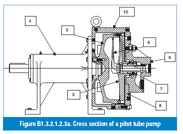
In general, pitot tube pump nomenclature is similar to that of an overhung impeller, separately coupled, single-stage, frame-mounted rotodynamic pump. Items unique to a pitot tube pump are identified as follows:
2. Rotor cover
3. Rotor
4. Bearing housing
6. Pitot tube
7. Mechanical seal
8. End bell
9. Manifold
10. Rotor casing