


Failures of submerged vertical pumps often occur without warning from the installed sensors and monitors because of the lack of transducers mounted where they can reliably sense the condition of the pump-down in the hole! Since there are no industrial standards that require sensors at the bottom of the pump, regardless of the power rating, the sensors are most often mounted on the motor, some distance from the pump. In the past, reduced efficiency and pump failure have not proven enough incentive for operators to properly instrument the system.
In today's economic climate, industries are pressured to operate their equipment longer and at improved efficiencies, while maintaining safe and reliable operation. This can be achieved in part by monitoring and trending of parameters such as vibration, lube oil condition, performance, exhaust gas analysis, etc. Vibration monitoring is probably the most important tool in these programs and has become accepted and proven worldwide in various industries. This article addresses the vibration monitoring of submerged vertical pumps that is now possible due to recent advancements in transducer installation.
Vertical Pump Monitoring
The monitoring methodologies in ISO 10816-1: 1995 Mechanical vibration - Evaluation of machine vibration by measurements on non-rotating parts recommend measuring at points that "significantly respond to the dynamic forces and characterize the overall vibration of the machine." However, most end-users consider it unreasonable to monitor every cutlass rubber bearing on the riser tube, and 10816-3: 1998 (E) recognizes the practical considerations that cause the points to usually be on "exposed parts of the machine that are normally accessible."
In fact, the measuring points suggested by 10816-1 (see Figure 1) are shown on only the bearing housings at the top of the machine; because the pump bowl/impeller region is not easily accessible, it is omitted. Therefore, many users of vertical pumps are unaware of the machinery information available "down the hole" and ignore, for what was formerly justifiable economic reasons, an essential source of data. In the case of vertical cooling water pumps, where the intake, pump bowl, impeller(s) and bearings that ISO strongly advocates monitoring, are all under water, the data must be collected by other than the usual methods.
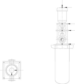 Figure 1
While the ISO 10816-1 standard only addresses measurements taken on non-rotating parts (the casing), there are good reasons to use proximity measurements of the shaft. For example, it is impossible to determine the amount of wear on the journal bearing caused by suspended particulate matter by using case-mounted transducers alone. No matter which transducer is selected to provide the data needed to manage the machine, it is likely that an effective, reliable installation package can be designed to simplify the process, reduce costs and economically justify monitoring machinery that, up to now, has been pumping some profits down the drain.
The machinery management regime selected by the user will dictate the need for permanent online systems for critical units or a portable data collector (PDC) on small pumps or multi-spare installations. Whether the data is collected via a PDC, or via permanent monitoring and management systems, there are methodologies available to help collect data from those previously inaccessible places.
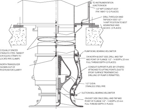 Figure 2
Information Is Missing or Attenuated
There are certain conditions and configurations where the pump vibration data can be picked up at the top of the motor. However, this "tail-wagging-the-dog" methodology has limitations; the signal will be attenuated by the different machine components between the pump and the motor and will be overlaid with the signal of the motor. For example, the detection of cavitation can only be carried out in the impeller/pump bowl region. Farther up the riser tube, flow-generated noise from the intermediate bearings adds to the cavitation signal and confuses the diagnosis. Since higher frequency signals attenuate faster than lower frequency signals, the data may not even reach the transducers (see Figure 5).
Results from several installations have shown that bearing and impeller condition data is readily available to transducers installed under water, close to the source of the data.
Why Would This Data Be Needed?
For a pump to be maintained at its optimum performance, regular inspection is recommended. Downstream indicators of the pump may exist that can show if the pressure or flow is below the required norm; if trended, they will give an indication that the pump should be withdrawn from service before unacceptable performance or failure occurs. The vibration data can be used to indicate the mechanical condition of the submerged bearings, what parts might need to be replaced and an appropriate maintenance schedule to minimize the cost of downtime.
The removal of the submerged section of a large vertical pump requires a great deal of preparatory work and the use of heavy mobile cranes. In some cases, the high cost of crane hire has been a deciding factor in the decision to instrument the submerged section of the pumps; the cost of instrumentation and monitoring is typically less than the charge to hire a heavy crane for one week. With monitoring installed, the decision to lift the pump for maintenance can be based on real data rather than on guesswork.
Considerations for Bearing Wear Monitoring
When XY proximity probes are installed to monitor pump bearing vibration and wear, a special probe protection package and modifications are required to make a successful installation. The proximity probe has to be packaged in a watertight outer casing that includes a ceramic cap. This cap provides a nonmetallic window that prevents the erosion of the probe tip. The thickness of the cap, 0.25- to 0.50-mm dependent on the transducer, reduces the effective linear range of the transducer.
The reduction of linear range means that less wear can be detected. With a 5-mm proximity transducer, the thickness of the ceramic tip reduces the range for diametral wear allowance to 1.5-mm or less. It may be appropriate to use a larger 11-mm probe, which offers a diametral wear allowance of up to 3.8-mm. In both cases, the probe setup is critical because the thickness of the end cap, while it decreases the physical range of the probe, does not lower the OK limit in the monitor. It is therefore possible for the shaft to contact the ceramic tip before this limit is reached. If this can occur, then a modification to the monitor may be required.
Mechanical modifications to the shaft and casing will also be significant; for example, a probe target ring , usually a nickel-based superalloy steel, must be attached to the shaft to minimize corrosion of the track that the probe views. Where the probe cable has to pass through the pump waterways, the conduit pipe for the probe cable should be attached to the leading edge of fixed spokes or the cable carried in drillings within these webs. Secure methods of attachment are mandatory.
Installation Pitfalls
While the installation of monitoring transducers on the submerged part of a vertical pump is relatively straightforward, there are several important points that need attention:
- Safety: Access to the submerged part of the pump is difficult and can be dangerous. Ensure that appropriate safety measures are in place before entering the intake pit.
- Turbulence: The areas surrounding the pump bowl and intake are subject to high turbulence, with significant force being generated by the swirling water. The transducer and the conduit must be securely attached to the surface, and the conduit attached to the pump body at frequent intervals. If the components that are torn off the pump by the turbulence are ingested, they will damage the impeller.
- Galvanic Corrosion: Some materials may actually promote corrosion. Choose the transducer housing and the conduit materials carefully to inhibit or prevent corrosion. They must be compatible with the materials found on the pump body and in the intake pit. Sacrificial anode blocks are particularly encouraged for seawater intake pumps.
- Protection of Electronics: Water and electronics do not mix well. Ensure that the transducer is properly protected against ingress of water that would lead to premature failure.
- Coatings: Many pump intakes, bowls, and riser tubes are treated with special corrosion-inhibiting coatings. Considerable care must be taken to repair and seal this coating when drilling through the metal below water level.
- Withdrawal Obstruction: The pump bowl may not have much clearance when it is inserted in or withdrawn from the foundation. The transducer may require a custom-engineered enclosure to keep it from interfering with the foundation.
- Wake Turbulence: Any conduit passing across the intake of the bearing will cause a wake. This wake will give rise to cavitation at the impeller, increasing the risk of erosion. Keep the conduit in line with struts or webs to prevent turbulence.
- Erosion: If the passage of particulate matter through the pump erodes the shaft, it will erode the probe tip, causing failure. Therefore, it is important to protect and package the probe with erosion-resistant materials.
Design and Development of a Reliable Installation Package
In 1995, GE's Bently Nevada applications engineers began designing and installing special transducers for the types of vertical pumps discussed in this article. In early trials, a standard velocity sensor was attached to the pump body, then covered with layers of glass fiber and epoxy resin. While this successfully protected the transducer, it eliminated the ability to carry out maintenance.
To address this shortcoming, they then adopted technology used on submarines: namely, placing the electronics in a sturdy housing completely filled with water-repellent grease. A standard velocity transducer housing was modified by adding a pressurized grease fitting and sealing the exit with a cable seal assembly (see Figure 3). These modifications to existing hardware and the new package designs for proximity probes and restricted access installations have made proactive management of a wider range of pumps and pump applications economically feasible.
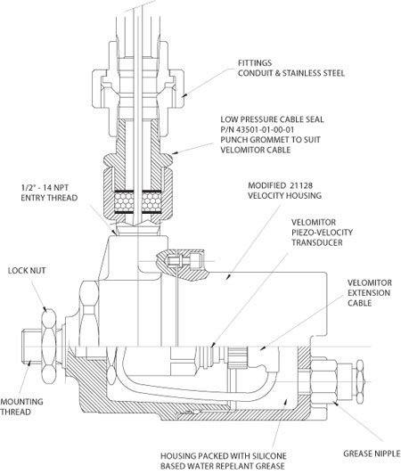 Figure 3. Saudi Aramco Trial Results
The custom transducer assemblies described above were provided to Saudi Aramco for a trial installation on six seawater intake cooling pumps at the Ras Tanura Refinery on the Arabian Gulf Coast. The year-long study was tasked with establishing solid evidence that the dynamic behavior of the pump is not documented by the data from transducers on the motors. A second task was to demonstrate instrumentation reliability.
Two additional transducers were mounted on the bottom of the mixed flow, 5-vane seawater pump (see Figure 4), in line with the original transducers on the motor. Signals were routed to a four-channel monitor with outputs for each sensor. Data was collected on a monthly basis with a two-channel portable spectrum and time domain analyzer.
The frequency and time domain data (see Figure 5) collected by Aramco shows a clear difference in readings taken from the sensors at the bottom of the pump and the top of the motor.
The pump data shows a high level of 1/2X component, especially in the in-line direction. This signal is highly attenuated in the motor data from the corresponding in-line direction transducer. The signal components around 340-Hz, thought to be associated with cavitation, are completely absent from the signals from the motor transducers.
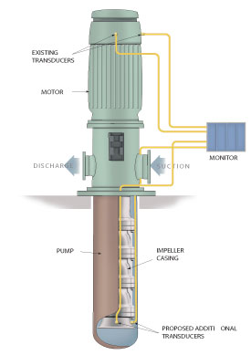 Figure 4
The Ras Tanura trials successfully demonstrated the effectiveness of the probes and the reliability of the instrumentation in adverse conditions. The Aramco engineers recommended installation of sensors at the bottom of submerged vertical pumps. As a result, the Saudi Aramco centrifugal pump standard, 31-SAMSS-004, now includes the monitoring requirement for open pit applications and plays a pivotal role in eliminating many pump failures that came without due warning.
SEC Follows Lead of Saudi Aramco
Many customers follow standards set by others in their region. As an example, Saudi Electric Company (SEC) specified that ten vertical seawater pumps on their Ghazlan II Power Plant were to be fitted with underwater monitoring. Close cooperation was maintained with the design and project engineers of the pump manufacturer, Weir Pumps of Glasgow, to reduce the impact on the manufacturing and supply schedules. While the main cooling water pumps (CWP) were fitted with identical transducer housings as used on the Aramco pilot project, the auxiliary CWP units, which must pass through a smaller foundation ring, required custom housings. These were designed and installed as part of the erection program.
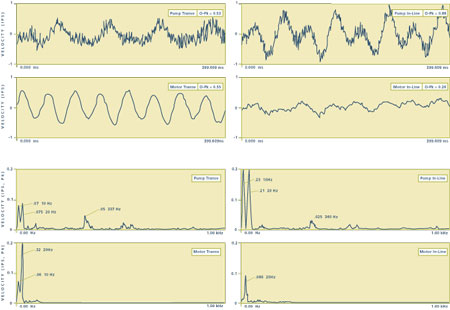 Figure 5
Summary
Vertical pumps are not typically considered critical when compared with main process or generating equipment. However, their failure can adversely impact production in many cases. With demands for increased profitability, the economic justification for monitoring any machine that can impact production also increases. While most would agree that the underwater section of vertical pumps should be monitored when a monitoring system can be justified, installing transducers on this section of the pump has previously been impractical due to the challenges of submerging these transducers. This article has demonstrated that capabilities now exist which make submerged transducers practical, and which provide excellent machinery protection and monitoring capabilities.
This article first appeared in ORBIT magazine. All material copyrighted GE Energy.