


Mechanical resonance is the tendency of a mechanical system to absorb more energy when the frequency of its oscillations (external excitation source) matches the system's natural frequency of vibration than it does at other frequencies. Mechanical resonance may cause violent swaying motions (large vibrational displacements) and even catastrophic failure (1).
External items in large vertical pumps that could excite a natural frequency are:
- Rotational unbalance
- Impeller exit pressure pulsations
- Gear couplings misalignment
Natural frequencies of a vertical pump and motor are calculated by performing a modal analysis using the Finite Element Method (FEM). The common name to refer to this kind of analysis is Finite Element Analysis (FEA). Typical software tools used at the Flowserve Santa Clara business unit for the analysis are ANSYS and Pro/ENGINEER. The primary reason for conducting an FEA is to obtain an acceptable separation margin between the unit operating speed and the individual structural natural frequencies.
FEA is based on a numerical method that some authors define as Galerkin's Method [Reddy, 1984]. A domain is divided into n number of subdomains, the elements, and equations of n grade are used to approximate the solutions of each subdomain. The accuracy of this numeric method depends on the number of subdomains into which the domain has been divided and the boundary conditions.
As associated with solving a differential equation, the accuracy of the FEA performed on a vertical pump and motor depends on the nature of the elements (in FEA software a considerable number of options are available for the analyst to select from depending on the purpose) and the boundary conditions applied to the model.
The element selection is not complex for an analyst with knowledge of the FEA software. Software like ANSYS, the one used by the Flowserve Santa Clara business unit, describes each element by the degrees of freedom, its particular properties, and its behavior and outputs.
On the other hand, the proper application of boundary conditions for a model requires knowledge and experience by the analyst. The analyst must not only possess the skills and knowledge about how to run the FEA software, but must also understand the behavior of the system modeled. In addition, an analyst must understand the significance of various actions and decisions that must be taken while modeling and running the analysis.
Background
During the spring of 2009, two large vertical pumps installed in a power generating plant experienced mechanical vibration problems associated with structural resonance.
The initial vibration amplitude of the pumps was found to be above the user's allowable vibration level. Preliminary solutions to the vibration problem affected the natural frequency values of the pump system, and a mechanical resonance condition appeared.
When the pumps were initially installed at the site, vibration readings were taken and a discrepancy was reported between the contractual limit of 0.157 in/s peak-to-peak and the measured vibration amplitude.
Before evaluating possible solutions to the problem, the pumps were bump tested to determine their structural natural frequency. Without water in the suction pit, the first structural natural frequency was 5.5 Hz, and the second natural frequency was 10.5 Hz. The second natural frequency is 23 percent higher than the operating speed of 514 rpm (8.5 Hz). As the suction pit was filled with water, the natural frequency values were reduced, since the water adds mass to the system. With the suction pit filled with water, a subsequent bump test showed a natural frequency at 8.5 Hz, which indicated that structural resonance was a contributing factor to the high mechanical vibration recorded when the pumps were operated.
The manufacturer proposed several different alternatives to shift the structural resonance and reduce the amplitude of the operating vibration. Since the second natural frequency coincided with the operating speed, a possible solution involved increasing the flexibility of the pump discharge head. Two methods to accomplish this task were evaluated-removing the external ribs from the discharge head or adding an external mass at the top of the motor.
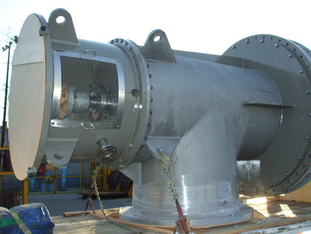
Figure 1. Discharge head with external ribs available on original design. Cutting the external ribs was a proposed solution for increasing flexibility of the discharge head.
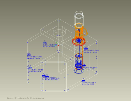
Figure 2. 3-D model of the pump.
The first step in the problem-solving process was to modify the FEA so that it agreed with the site bump test results. Cutting the external ribs would reduce the stiffness of the discharge head to mounting plate connection, which would lower the natural frequency value. The model was updated to simulate removal of the external ribs, and the analytical results showed that the natural frequency value decreased. Unfortunately, the reduction was not sufficient to provide the desired separation margin between the pump operating speed and the pump system natural frequency.
The next step was to model adding an external mass at the top of the motor. The pump manufacturer's standard is to procure motors capable of having external weight added to the top of the motor that is equal to 20 percent of the motor weight without affecting the structural integrity of the mechanical operation of the motor.
The pump motor's manufacturer was aware of this requirement and approved the installation of a 2,000-lb. weight at the top of the motor.
Figures 3 and 4 show the bump test results of these two modifications.
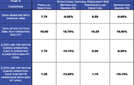
Figure 3. Natural frequency values of pump A.
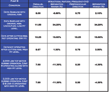
Figure 4. Natural frequency values of pump B.
Figures 3 and 4 show that the resonant condition still exists with the addition of mass at the top of the motor and the cut external ribs. Although the pumps and motors are identical, the bump test results show differences attributed to foundation differences.
Figures 5 and 6 provide the operational vibration amplitudes associated with the two modifications for the A and B pumps.
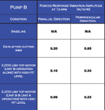
Figure 5. Vibration amplitude values of pump A.
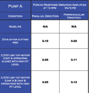
Figure 6. Vibration amplitude values of pump B.
After cutting the external ribs and adding the extra weight, the operational vibration amplitude readings for pump A are within the contractual limits; however, pump B was not within the contractual limits.
Figures 7 and 8 show the deflected mode shapes from the FEA for the modes closest to the operating speed. These deflected mode shapes show that the major deflection is occurring in the portion of the pump below the pump baseplate. Consequently, the initial modifications to the portions of the pump above the pump baseplate were not as effective as expected.
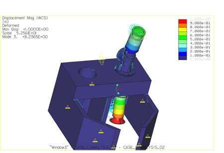
Figure 7. Third mode (8.23 Hz parallel) close to pump operating speed.
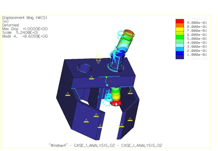
Figure 8. Fourth mode (8.60 Hz perpendicular) close to pump operating speed.
Several other alternatives were evaluated such as increasing the size of the coupling access holes in the pump discharge head, adding mass to the pump's lower portion, adding a lateral restraint to the lower portion of the pump, and adding a spring plate between the pump and motor. Each of these alternatives was evaluated through FEA, and the practicality of its application was discussed with the user. A decision was made to pursue the spring plate alternative.
Spring plates are mechanical devices consisting of two circular plates with an engineered gap in the area between them. One plate is attached to the pump discharge head, and the other is attached to the motor mounting flange.
The design of the spring plates is performed using proprietary software developed by the pump manufacturer.
To ensure that the spring plates provided the expected results, one set of plates was manufactured and installed on pump A as shown in Figure 9.
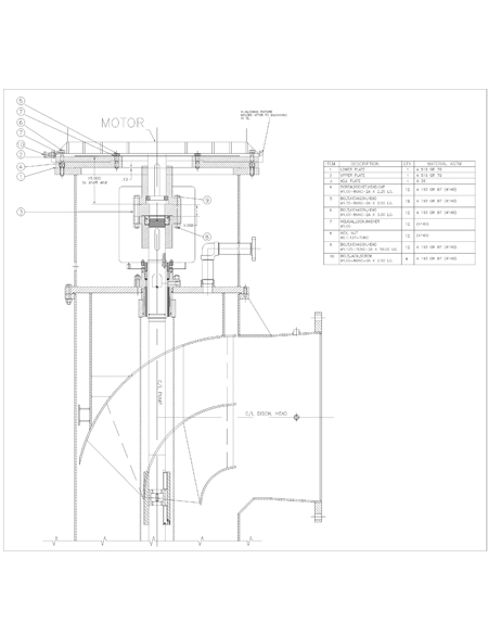
Figure 9. Spring plates design and assembly installed on the pumps.
The spring plate modification was performed. The pump was bump tested to determine the actual natural frequency values, and the operational vibration values were recorded.
Pump B, which exhibited the higher operational vibration values, decreased to 0.11 in/s peak-to-peak for perpendicular direction and 0.10 in/s peak-to-peak for parallel direction measured at the top of the motor. In addition, the natural frequency separation ratio was increased to more than 15 percent, which was accepted by the end user.
Solution
For this case, the objective was to decrease the stiffness of the mechanical system.
The first step was to fine-tune the FEA model to match the on-site bump test results for the pumps. When this was completed, proposed changes could be evaluated with the FEA model. Removing external ribs and adding extra weight at the top of the motor were preliminary solutions, but when it was determined that a significant weight was needed, this option was abandoned.
Spring plates were the best solution, considering that the solution was designed to reduce the discharge head stiffness, and only the above-ground parts of the pump system need modification.
The ease of design and manufacture of spring plates are important advantages of these devices when a mechanical resonance exists in pumps already installed at the user's site. The incorporation of spring plates into installed pump systems affects only assemblies of the motor and motor support interface and the motor-to-pump coupling. Piping and foundation work need not be disturbed.
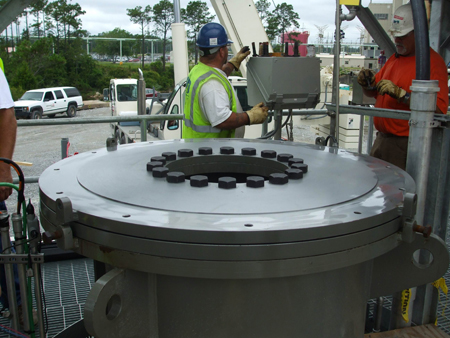
Figure 10. Spring plates installed on motor support. Note the existence of the gap between both plates.
Conclusion
The finite element modeling and analysis techniques provide an understanding of the mechanical system behavior, including the natural frequency values during design phase.
Understanding the predicted natural frequency values allows an evaluation of the expected separation between the pump natural frequency and excitation frequencies, such as pump operation speed. The separation is established by the pump manufacturer to avoid mechanical resonance.
The boundary conditions assumed during FEA are essential to the accuracy of predicted results. In some cases, the final as-built conditions (such as foundation stiffness) significantly affect the analysis accuracy if they differ from those conditions assumed during the analysis.
When this happens, it is necessary to perform a bump test to know the actual natural frequencies of the pump systems after they are installed on site. Using the results of the bump tests, the finite element model must be tuned to match the results obtained on site. Proposed solutions can then be simulated and analyzed.
It is important to know the type of acceptable solution that will provide the best pump operation. In some cases, results from the bump test indicated that increasing the natural frequency of the system was the best solution. The increase in natural frequency could be accomplished by modifying two of the pump system's physical characteristics, reducing mass or increasing stiffness of the system.
In this example, increasing the separation between the pump system natural frequency and the excitation frequency (pump rotational speed) required that the pump system natural frequency be reduced. Spring plates were installed to increase the flexibility of the upper pump structure, thus reducing the natural frequency.
Spring plates are optimized solutions when the pumps are installed on site and the user requires a fast and effective solution without removing the pumps or modifying the site infrastructure. Finite element analysis and design tools, combined with simple materials and manufacturing methods, provide the customer with a quick, effective solution.
References
1. Singiresu, S. Rao, Mechanical Vibrations, Addison Wesley, 2003.
2. Reddy, J.N., An Introduction to Finite Element Method, McGraw Hill, 1984