


For businesses striving to achieve restorative and sustainable practices that harmonize with regulatory compliance, knowledge of best available practices is a baseline requirement. As these businesses then consider implementation of best available technologies, their cost-to-benefit ratio must be assessed before moving in that direction. Accordingly, competent business leaders are also factoring in their projections of changing demands and anticipated marketplace requirements. Understandably, projects that result in highest benefits in both competitive and sustainable returns, while highest on the leaders’ list of priorities, will prove challenging. However, well-supported benchmarking will be helpful. Also, input from experienced, trustworthy and competent technology providers has facilitated maintaining the needed focus and has often accelerated the decision-making processes. The sealing of process pumps is a case in point, as the following pages will show.
Suppose a brewery or other large-scale beverage producer is late in discovering that a competitor found ways to cut back on its use of water, while at the same time increasing its profit margins. In that case, the one that was slow in implementing the exact methods used by their more-profitable competitors will pay dearly for their procrastination.
This article describes how forward-looking beverage producers are now using well-proven water management approaches that increase pump life, cut back on water use and demonstrably increase profitability. This article depends on informative compilations by the Beverage Industry Environmental Roundtable (BIER) to report factual data in this article; BIER’s input is greatly appreciated.
Beverage Industry Environmental Roundtable Data
Water conservation is a core element of sustainability programs. Not long ago, the BIER published its annual benchmarking study with trends and observations. For 10 years, the study has benchmarked production, water, energy and emissions for more than 1,600 global facilities.
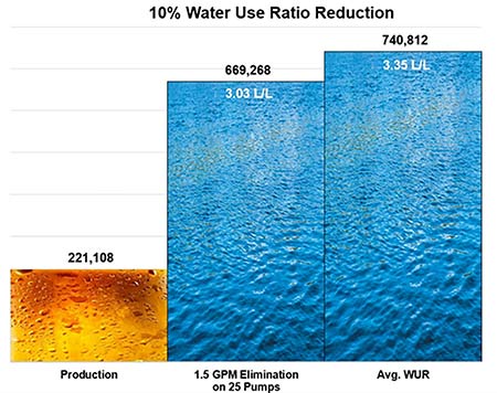
A key metric is the water use ratio (WUR), also known as L/L, which is the ratio of total water used to final product delivered. In the BIER’s January 2019 report, there were 453 breweries reporting and 83% of those were labeled “beer only” producers. The WUR for these was given as 3.35 L/L for all those reporting and 3.39 L/L for the “beer only” group. Overall, the WUR benchmark has seen a 9% average improvement each year for the 2017 to 2019 time frame (Header Image).
Advanced Sealing for Process Pumps
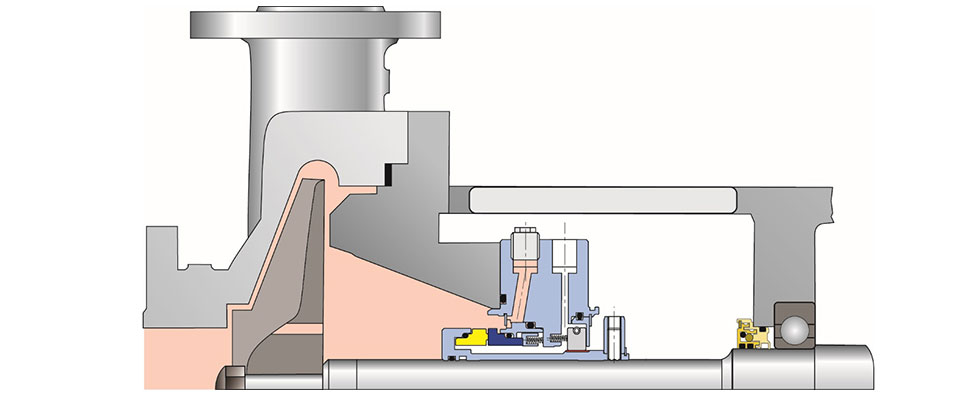
Pumps used in brewing processes use face seals that are classified as either single, shown in Image 2 with American Petroleum Institute (API) Flush Plan 03, or dual mechanical seals, shown in Image 3 with a cartridge-style dual mechanical seal and API Flush Plan 54. Between 20% and 30% of all brewery pumps will use dual seals for pumping services such as hot wort, mash, kettle and adjunct as well as clean-in-place (CIP) pumps. All seals require either a thin film of water or gas to prevent face-to-face contact and seal overheating. But aside from the 9% average yearly improvement in WUR, a further 10% reduction in WUR can be achieved by modifying and upgrading the traditionally employed seal piping plans in just 25 of the many pumps found in a brewery.
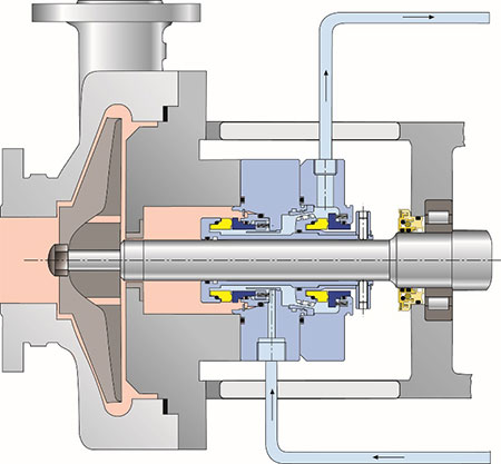
Dual seals cannot function without a secondary fluid acting as a lubricating buffer or barrier to provide both fluid film face separation and cooling. API Plan 55 is used on dual seals at a flow rate of 1.5 gallons per minute (gpm) to provide a buffer fluid of clean water between the inner and outer seal faces (Image 4). However, where Plan 55 usually discharges its buffer fluid to drain, the elimination of flow-to-drain on just 25 pumps will reduce the WUR by roughly 10%, based on data averages found in the BIER benchmark study.
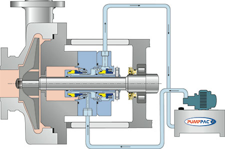
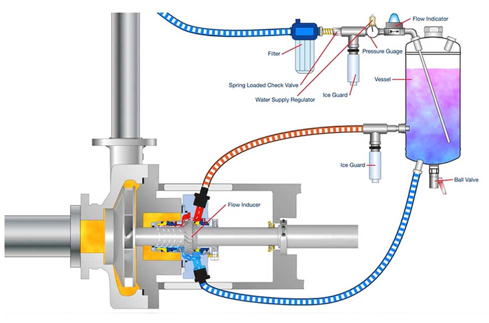
Accordingly, the WUR reduction strategy is to use a water management system instead of the API Plan 55 depicted in Image 4. Water management systems (Image 5) are a modified API Plan 53-A: They are closed systems designed to eliminate the need for operator intervention to maintain the seal pot. The clean water is isolated by a seal support system and recirculated by an internal flow inducer and/or through thermal convection. This means that city water is not lost to the drain—moreover, mean time between failure (MTBF) is extended because each pump is regulated separately. An optimal barrier fluid pressure is chosen to ensure that a clean fluid film exists at all times between its sets of seal faces.
Pressure optimization of the process fluid is required because mash and wort are known to be abrasive. The inner seal faces are precision lapped to one helium light band with an inner seal face rotating against a stationary face. The face set is spring-energized and hydraulic closing forces with properly engineered sealing pressures divided by mean face velocities (p/v ratios) will create a thin fluid film. If the city water buffer enters at a pressure lower than the process fluid, an abrasive process liquid is likely to intrude and establish the fluid film. This means the process fluid eventually cross-contaminates the secondary buffer seal water, which is why it cannot be reused in the seal water loop and, instead, is discharged to the drain. However, by increasing the pressure of the secondary seal water, clean city water becomes the fluid film, which increases the life of the mechanical seal. This requires provisions to pressurize each application differently at each pump. Individual pressurization capability is the primary difference between API Plan 55 and API Plan 54.
CIP and similar maintenance facilitators point to the wisdom of specifying easy-to-clean features and components. A well-proven seal support vessel is shown in Image 5. Its quick-release clamp makes it easy to open, inspect, clean and reclose the vessel.
Amending Prevailing Industry Standards
To achieve a 10% improvement in WUR, well-informed breweries have added an amendment/addition to current equipment industry standards. The amendment stipulates the following:
- A mechanical seal support system must be provided as a pre-engineered turn-key system: it must include all instrumentation and fittings necessary to install at the site.
- The tank capacity must be a minimum of 10 liters (2.64 gallons), designed to the American Society of Mechanical Engineers (ASME) VIII Div. 1 and pressure equipment directive (PED). Wetted surfaces must have filler welds to eliminate bug traps.
- A quick-release clamp must be used to allow the bottom section of the vessel to be removed for cleaning and inspection. This will give greater control over applications that require higher standards of cleanliness or where product quality cannot be compromised.
- The unit must be self-filling and incorporate a quick disconnect coupling to allow for inspection and cleaning.
- A flow indicator must be provided to allow visual monitoring of inner seal face integrity.
- The system must deliver barrier fluid at pressures 15 pounds per square inch gauge (psig)/103 kilopascals (kPa) minimum above the process pressure in the pump stuffing box and regulation means/devices must be located at the seal pot.
- The seal system must include in-line filtration of city/plant seal water to one micron. An internal standpipe on the supply leg, a three-way valve on the return leg, and a blow-off valve at the bottom of the tank must be included to allow clearing the system of any contamination after initial installation and over the life of the application.
- As part of the initial supply package, documentation must include a heat generation report for each installation. The report must detail the operating conditions for the intended shaft diameter, speed, process/barrier pressure, temperature and induced flow. The data must include or summarize the input needed for thermal equilibrium estimation and for calculating the heat generated by the specific seal supplied in each case.
In conclusion, the WUR is an important metric for the beverage industry. Addressing API piping plan options can yield a 10% improvement on just 25 pump applications. The BIER benchmark shows an average 9% annual WUR reduction for the industry from 2015 to 2017, presumably spread across a number of improvement strategies. Modifying the API piping plan is a way to drive down the WUR. In virtually all cases, the payback will be rapid. Experienced manufacturers can assist users in calculating the money saved by implementing modern water management systems in the beverage industries worldwide.
References
1. wwww.bieroundtable.com/wp-content/uploads/2018-Water-and-Energy-Use-Benc…