


Motor protection in industrial applications has come a long way over the past 30 years, from bimetallic and eutectic alloy overloads to basic solid-state overloads and what are often referred to today as motor management relays. Motor management relays are a step above standard solid-state overloads, providing more sophisticated motor protection features, better diagnostics and a greater variety of high-end optional features.
Solid-State Overload Relays
A basic solid-state overload relay protects a motor by opening a 95/96 fault contact. Either the fault contact is closed indicating that there is not a trip condition present, or it is open indicating that a trip condition is present. There is no control capability. Control must be added in series with the fault contact that is wired to the contactor coil for control and protection of a motor.
Solid-state overloads often come in two varieties. Low-end relays only monitor current and higher-end relays monitor current, voltage and, therefore, calculate power as well. The higher-end relays provide additional protections such as over and under voltage, low and high power, and voltage phase loss and voltage unbalance. Detecting pump cavitation is a feature often provided for low power.
These features and many more are offered with motor management relays.
Motor Management Relay Features
Although the additional optional features offered by manufacturers vary, one of the major features that distinguish motor management relays from basic overload relays is the selection of various operation modes. These modes vary by manufacturer, but most include:
- Overload—the relay acts as a basic overload relay.
- Direct—the relay acts as a full voltage nonreversing (FVNR) motor starter with control and protection.
- Reverser—the relay acts as a full voltage reversing (FVR) motor starter with control and protection.
- 2-Speed—this single motor management relay controls and protects both the fast and slow motor.
- Star/Delta—where the relay’s firmware takes care of all the timing and control of the three contactors, eliminating the need for external timing relays.
The features required for specific applications often determine which motor management relay is used.
Motor Protection Features
High and low limits are typically set with default values for each protection, but these limits are typically configurable to meet any application needs.
These additional motor protection features associated with motor management relays generally include the following:
1. Ground fault (GF) protections such as an additional GF module with a zero sequence current transformer (CT) for accurate measurement of ground currents down to 30 milliampere (mA). This is a common feature of most motor management relays.
Another feature that is less common, but which can be a powerful GF feature, is a GF pulse detect feature. This feature detects and locates ground faults on high resistance ground (HRG) pulsed systems without a separate GF module or zero sequence CT. This automatic detection of the ground fault source saves a considerable amount of time determining the location of the ground fault.
2. Frequency monitoring to detect frequency deviations.
3. Power factor deviation monitors the PF on the supply side of the load and will trip the motor if the measured deviation from rated exceeds the set threshold.
4. Peak demand is typically a warning rather than a trip. It is provided to indicate if the peak demand exceeds a specified threshold.
5. There are many names for this feature, but it will be referred to here as under voltage restart. The feature is designed to safely reclose any contactor(s) that has opened during a voltage loss event. A voltage loss restart algorithm allows facilities to implement automatic staggered restart of motors following a voltage loss or voltage dip without manual intervention or programmable logic controller (PLC) programming.
There are other optional protection features, but these represent some of the most common.
Integrated Logic
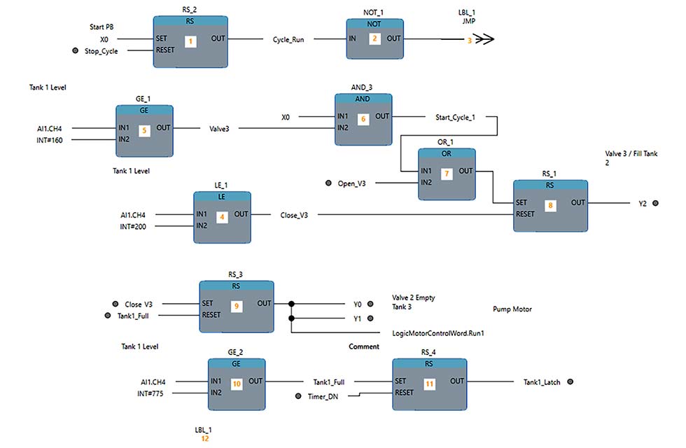
Many motor management relays include an integrated logic engine. There is no limit to the number of control requirements that can be solved with onboard logic. Often, this logic engine can be used as a control source for the motor management relay.
Applications such as time-of-day control and specific control functionality, normally not provided with overload relays, can be implemented. In some cases, even an external PLC can be eliminated such as for remote pump stations in water/wastewater applications, saving considerable cost.
The integrated logic allows specific functions to be executed locally for fast reaction to specific protection requirements, as well as to offload these functions from a main PLC.
Expansion I/O
Motor management relays also generally include the addition of optional expansion input and output (I/O) modules. These include digital I/Os, analog I/Os as well as temperature input modules such as the thermocouple and resistance temperature detector (RTD). This expansion I/O capability, coupled with the integrated logic engine, provides another level of local control and protection features.
- Digital inputs can be used when temperature, pressure and other similar inputs are required as interlocks for motor protection.
- Digital outputs can be used to control alarm horns, pilot lights or even solenoids.
- Analog inputs can be used to monitor 4-20 ma or 0-10 volts direct current (vdc) inputs from pressure tanks or any other device that provides a voltage or current analog signal.
- Analog outputs can be used to provide motor currents, voltages, power or any other analog value to the main PLC with a 4-20 ma or 0-10 vdc analog signal.
- Temperature inputs allow the local logic engine or the main PLC to monitor bearing or winding temperatures from critical motors.
In most cases, the I/O can be monitored and controlled by either the local logic engine in the motor management relay or by the main PLC via a network. Either way, expansion I/O saves the cost of adding additional I/O as a separate node on a network and the need to provide an additional enclosure for that I/O.
For critical motors requiring high-end protection features or any motor applications requiring additional high-end features, motor management relays can be worth a slightly higher cost. Many manufacturers price their motor management relays at or slightly above the higher-end basic overload relays, making them a good choice for most motor control and protection applications.